


SFP Transceiver
Installation Guide
1000BASE-SX (3CSFP91)
1000BASE-LX (3CSFP92)
1000BASE-T (3CSFP93)
1000BASE-LH70 (3CSFP97)
Copyright © 2003, 3Com Corporation. All rights reserved.
No part of this documentation may be reproduced in any
form or by any means or used to make any derivative
work (such as translation, transformation, or adaptation)
without written permission from 3Com Corporation.
3Com Corporation reserves the right to revise this
documentation and to make changes in content from
time to time without obligation on the part of
3Com Corporation to provide notification of such revision
or change.
3Com Corporation provides this documentation without
warranty, term, or condition of any kind, either implied or
expressed, including, but not limited to, the implied
warranties, terms, or conditions of merchantability,
satisfactory quality, and fitness for a particular purpose.
3Com may make improvements or changes in the
product(s) and/or the program(s) described in this
documentation at any time.
3Com registered trademarks are registered in the United
States and may or may not be registered in other
countries. 3Com and the 3Com logo are registered
trademarks of 3Com Corporation.
All other company and product names may be trademarks
of the respective companies with which they are
associated.
Part No. DIASFP91-AAA03
Published October 2003
Introduction
This guide covers installation, removal and technical
information for the
■ 1000BASE-SX SFP Transceiver (3CSFP91)
■ 1000BASE-LX SFP Transceiver (3CSFP92)
■ 1000BASE-T SFP Transceiver (3CSFP93)
■ 1000BASE-LH70 SFP Transceiver (3CSFP97)
Each transceiver, when installed into a 3Com Switch,
provides a high-speed Gigabit Ethernet connection. They
can be installed and removed with your system powered
up.
Installation and Removal
Safety Precautions
Be sure you follow all safety precautions when you install
or replace an SFP Transceiver. To avoid electric shocks and
burns to yourself and damage to the equipment, read and
follow these warnings:
WARNING: When the system is on:
■ Never insert a metal object such as a screwdriver or
a finger with jewelry into open module slots
■ Do not touch any connections inside the chassis
with your hands or fingers.
WARNING: Fiber Optic ports - Optical Safety.
Never look at the transmit laser while it is powered-
up. Never look directly at the fiber TX port and fiber
cable ends when they are powered-up.
WARNING: Use of controls or adjustments of
performance or procedures other than those
specified herein may result in hazardous laser
emissions.
WARNING: RJ-45 Ports. These are shielded RJ-45
data sockets. They cannot be used as standard
traditional telephone sockets, or to connect the unit
to a traditional PBX or public telephone network.
Only connect RJ-45 data connectors, network
telephony systems, or network telephones to these
sockets.
Either shielded or unshielded data cables with
shielded or unshielded jacks can be connected to
these data sockets.
AVERTISSEMENT: Quand le systeme est allumé:
■ Ne jamais introdure d'objet métallique, tel qu' un
tourne vis ou meme votre doight si vous portez un
bijou dans le reserve au module.
■ Ne touchez aucun engrenage à l' interieur du
chasis avec le doight ou la main.
AVERTISSEMENT: Ports pour fibres optiques –
sécurité sur le plan optique.
Ne regardez jamais le laser tant qu'il est sous tension.
Ne regardez jamais directement le port TX
(Transmission) à fibres optiques et les embouts de
câbles à fibres optiques tant qu'ils sont sous tension.
AVERTISSEMENT: L'utilisation de contrôles, de
réglages de performances ou de procédures autres
que ceux qui sont spécifiés au sein du présent
document risquent d'entraîner l'exposition à des
rayonnements laser dangereux.
AVERTISSEMENT: Points d’accès RJ-45. Ceux-ci sont
protégés par des prises de données. Ils ne peuvent
pas être utilisés comme prises de téléphone
conventionnelles standard, ni pour la connection de
l’unité à un réseau téléphonique central privé ou
public. Raccorder seulement connecteurs de
données RJ-45, systèmes de réseaux de téléphonie
ou téléphones de réseaux à ces prises.
Il est possible de raccorder des câbles protégés ou
non protégés avec des jacks protégés ou non
protégés à ces prises de données.
VORSICHT: Wenn das Betriebssystem angeschaltet
ist:
■ Führen Sie niemals einen Metallgegenstand wie
z.B. einen Schraubenzieher oder einen beringten
Finger in den offenen Modulschlitz ein.
■ Berühren Sie keine Verbindungen innerhalb des
Gehäuses mit Ihren Händen oder Fingern.
VORSICHT: Faseroptikanschlüsse – Optische
Sicherheit.
Niemals ein Übertragungslaser betrachten, während
dieses eingeschaltet ist. Niemals direkt auf den Faser-
TX-Anschluß und auf die Faserkabelenden schauen,
während diese eingeschaltet sind.
VORSICHT: Die Verwendung von Steuerelementen
oder die Anpassung von Leistungen und Verfahren in
anderer als der hierin genannten Weise kann zu
gefährlichen Laseremissionen führen.
VORSICHT: RJ-45-Porte. Diese Porte sind geschützte
Datensteckdosen. Sie dürfen weder wie normale
traditionelle Telefonsteckdosen noch für die
Verbindung der Einheit mit einem traditionellem
privatem oder öffentlichem Telefonnetzwerk
gebraucht werden. Nur RJ-45-Datenanscluße,
Telefonnetzsysteme or Netztelefone an diese
Steckdosen anschließen.
Entweder geschützte oder ungeschützte Buchsen
dürfen an diese Datensteckdosen angeschlossen
werden.
Handling SFPs
To prevent potential damage from electrostatic discharge,
always observe the following when handling SFP
Transceivers:
■ Always wear an anti-static wristband connected to a
suitable earth point.
■ Do not remove an SFP Transceiver from its packaging
until you are ready to install it into a switch.
■ Do not touch any of the pins, connections or
components of an SFP Transceiver.
■ Always store or transport an SFP Transceiver in anti-
static packaging.
Regulatory Compliance
Laser Eye Safety: FDA 21(J) CFR, EN 60825-1/2.
Electrical Safety: EN/UL 60950
Inserting the Transceiver
The SFP Transceiver is keyed and there is only one way in
which it can be installed correctly. It is not necessary to
power-down your Switch.
1 Read and follow all safety precautions stated earlier in
this guide.
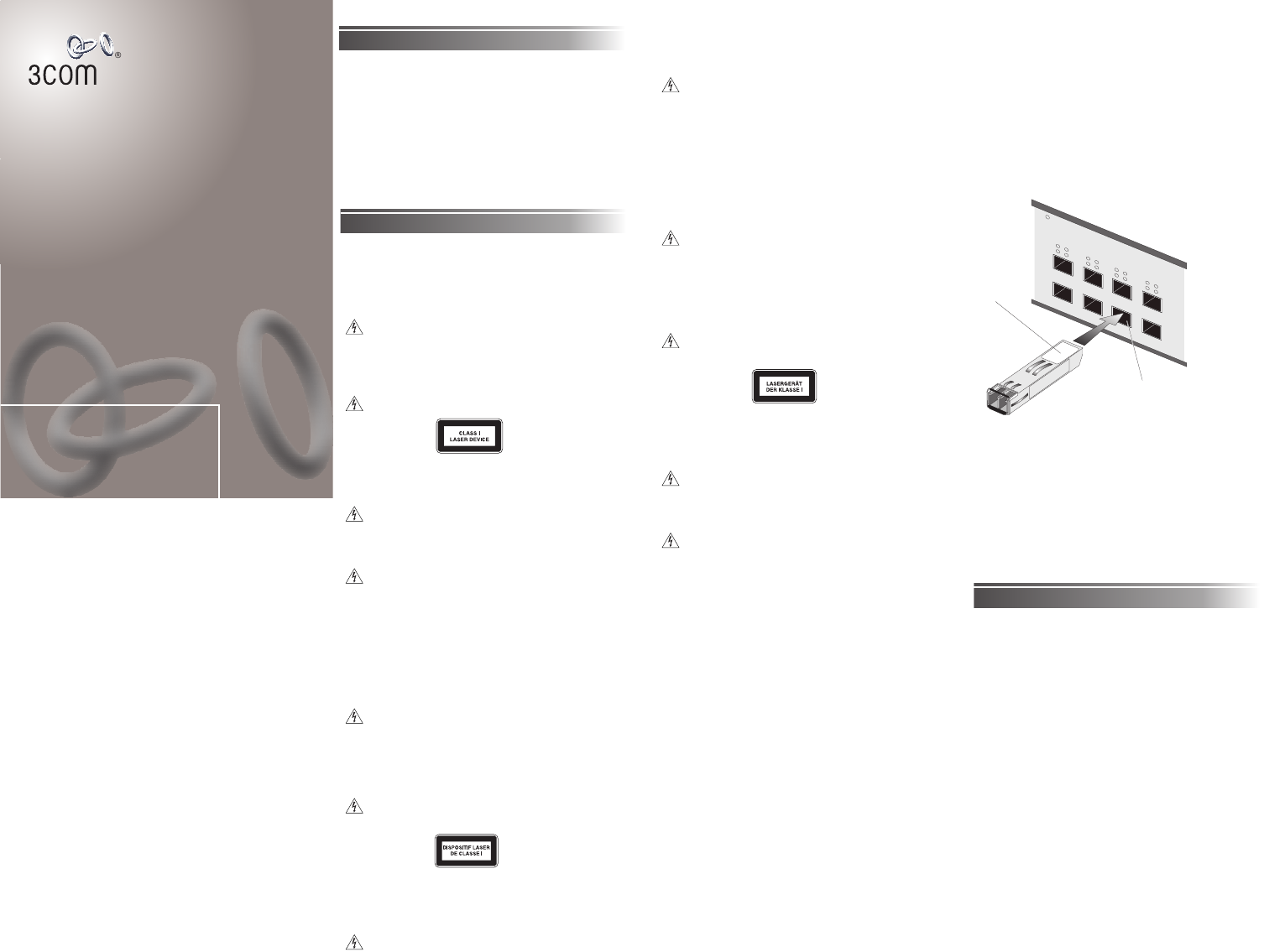
2 Hold the transceiver so that the connector is toward
you and the product label is visible. Ensure the wire
release lever is closed (in the upright position). See
Figure 1.
3 Gently slide the transceiver into the SFP port until it
clicks. If the transceiver does not click into place,
remove it, turn it over and re-insert.
4 Remove the plastic protective cover if fitted.
5 Use an appropriate cable to connect the transceiver to
a suitable device.
Figure 1 Inserting the Transceiver (for example purposes
only, this figure shows a 1000BASE-SX SFP Transceiver)
Removing the Transceiver
It is not necessary to power-down your Switch.
1 Disconnect the cable from the transceiver.
2 Move the wire release lever downwards until it is
pointing toward you.
3 Pull the wire release lever toward you to release the
catch mechanism; the transceiver will then easily slide
out.
Problem Solving
If you suspect a problem, carry out these steps before
contacting your supplier:
■ Refer to the documentation supplied with your Switch
for general problem solving information.
■ Ensure that you have followed the installation
instructions in this guide, and the transceiver is correctly
installed in the Switch.
■ Ensure that the Switch in which the transceiver is fitted
is powered-up.
■ Ensure that the device at the far end of the link is
powered-up and operating correctly.
■ Ensure that all connectors on the fiber optic segment
are correctly engaged (1000BASE-SX, 1000BASE-LX,
1000BASE-LH70 SFP Transceivers only).
■ Clean the fiber terminators by wiping them gently with
a clean tissue or cotton bud moistened with a little
ethanol. Dirty fiber terminators on the fiber optic
segment impair the quality of the light transmitted
through the cable (1000BASE-SX, 1000BASE-LX,
1000BASE-LH70 SFP Transceivers only).
■ To remove an LH70 SFP Transceiver that has been
inserted with the wire release lever pointing down, push
the blue plastic at the base of the transceiver inwards
towards the unit to release the catch mechanism.
For information about obtaining technical support, refer
to "Technical Support" in this guide.
Temperature
On = enabled, link OK Flashing = disabled
P=
P
a
ck
e
t
S=
S
ta
tu
s
5678
17 18 19 20
17
5
P
S
P
S
18
6
P
S
P
S
19
7
P
S
P
S
20
8
P
S
P
S
Product
label
Suitable port
on host Switch