5-16 C
HAPTER
5: A
DVANCED
M
ANAGEMENT
STP Configurations
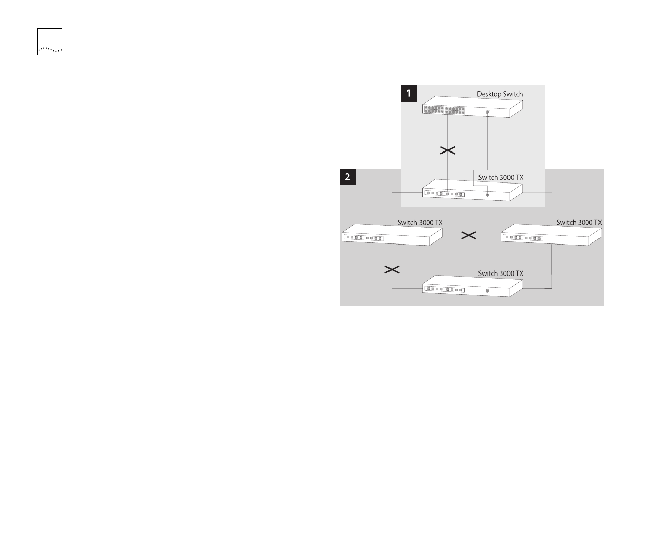
Figure 5-12 shows two possible STP configurations
using SuperStack II Switch units:
■
Configuration 1 — Redundancy for Back-
bone Link
In this configuration, a Desktop Switch and
Switch 3000 TX both have STP enabled and are
connected by two Fast Ethernet links. STP discov-
ers a duplicate path and disables one of the links.
If the enabled link breaks, the disabled link
becomes re-enabled, therefore maintaining con-
nectivity.
■
Configuration 2 — Redundancy through
Meshed Backbone
In this configuration, four Switch 3000 TX units
are connected such that there are multiple paths
between them. STP discovers the duplicate paths
and disables two of the links. If an enabled link
breaks, one of the disabled links becomes
re-enabled, therefore maintaining connectivity.
Figure 5-12
STP configurations


