


OfficeConnect
®
Wireless 11b Cable/DSL Gateway
(3CRWE53172)
About This Guide:
This Guide takes you through the basic steps necessary to install and
configure your OfficeConnect Wireless 11b Cable/DSL Gateway, and
establish a connection from your computers to the Internet. Throughout this
guide the OfficeConnect Wireless 11b Cable/DSL Gateway is simply referred
to as the Gateway.
Note: 3Com recommends that the Gateway is configured from a wired
Ethernet computer during the initial set-up.
Your package contains:
•
One OfficeConnect Wireless 11b Cable/DSL Gateway
•
One power adapter for use with the Gateway
•
Four rubber feet
•
One Ethernet cable
•
One CD-ROM containing the Gateway Discovery program and the User Guide
•
This Installation Guide
•
One Support and Safety Information Sheet
•
One Warranty Flyer
System Requirements
Before starting, you must ensure the following:
•
You already have a cable or DSL broadband connection to the Internet, with a
suitable modem, and that this connection works properly. The modem must
have an Ethernet port for connection to your Gateway.
•
You have a computer that has an Ethernet connection available and is
already correctly configured for communication with the Internet. Your
computer must be able to connect to the Internet via the modem, and
must have a Web browser installed.
•
There are no other DHCP server devices on your local network that are
responsible for allocating IP addresses to your computers and other network-
connected devices. Your Gateway will now perform this function by default.
•
You have a computer with a wireless 802.11b or 802.11b adapter card installed.
If one or more of these conditions are not met, refer to the comprehensive Gateway
User Guide provided on the accompanying CD-ROM for further guidance.
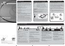
INTRODUCTION
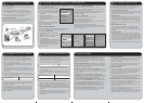
When positioning your Gateway, ensure:
• The unit is centrally located to the wireless computers that will connect
to the Gateway. A suitable location might be on top of a high shelf or
similar furniture to optimise wireless connections to computers in both
horizontal and vertical directions, allowing coverage throughout.
• In order to meet FCC radiation exposure regulations the Gateway should be
located in a position that maintains a minimum distance of 20 cm (8 inches)
from any personnel (refer to the User Guide for details).
• It is out of direct sunlight and away from sources of heat.
• Cabling is away from power lines, fluorescent lighting fixtures, and
sources of electrical noise such as radios, transmitters and broadband
amplifiers.
•Water or moisture cannot enter the case of the unit.
• Air flow around the unit and through the vents in the side of the case
is not restricted. We recommend you provide a minimum of 25 mm
(1 in.) clearance.
Installation Guide
POSITIONING YOUR GATEWAY
Dimensions and Operating Conditions
* Refer to Regulatory Notices section in the Support and Safety Information sheet
Wireless 11b Cable/DSL
Gateway 7VA,
23.9 BTu/hr power
requirement
0 to 40ºC (32 to 105ºF)
operating
temperature
0 to 90% (non-
condensing) humidity
Wireless 11b
Cable/DSL Gateway
592 g (1.3 lb)
O
f
f
i
c
e
C
o
n
n
e
c
t
W
i
r
e
le
s
s
C
a
b
l
e
/
D
S
L
G
a
t
e
w
a
y
3
CR
WE
5
1
1
9
6
L
A
N
S
t
a
t
u
s
C
a
b
l
e
/
D
S
L
W
i
r
e
l
e
s
s
A
l
e
r
t
DIMENSIONS AND STANDARDS
Standards
Functional: ISO 8802/3, IEEE 802.3, 802.3u, 802.11b, WiFi
Safety: UL 1950, EN 60950, CSA 22.2 #950, IEC60950
EMC: EN 55022 Class B, EN 55024, FCC Part 15 Class B*
ICES-003 Class B, CNS 13438 Class A, ETS 300-826
Environmental: EN 60068 (IEC 68)
Radio: CFR47 FCC Part 15.207, 15.209, 15.247 and 15.249
ETS 300 328 (2.4 Ghz ISM band Wide band transmission systems)
3Com Corporation, Corporate Headquarters, 5500 Great America Parkway, P.O. Box 58145,
Santa Clara, CA 95052-8145
Copyright © 2003 3Com Corporation. All rights reserved. 3Com, the 3Com logo, and OfficeConnect
are registered trademarks of 3Com Corporation.
Microsoft, MS-DOS and Windows are registered trademarks of Micorsoft Corporation.
All other company and product names may be trademarks of their respective companies.
Part number: DIA5317-2AAA01 Published: July 2003
Using the Rubber Feet
Use the four self-adhesive rubber feet to prevent your Gateway from moving around
on your desk or when stacking with other flat top OfficeConnect units. Only stick
the feet to the marked areas at each corner of the underside of your Gateway.
Safety Information
WARNING: Please read the ‘Important Safety Information’ section in the
Support and Safety Information sheet before you start.
VORSICHT: Bitte lesen Sie den Abschnitt ‘Wichtige Sicherheitsinformationen’
sorgfältig durch, bevor Sie das Gerät einschalten.
AVERTISSEMENT: Veuillez lire attentivement la section "Consignes
importantes de sécurité" avant de mettre en route.
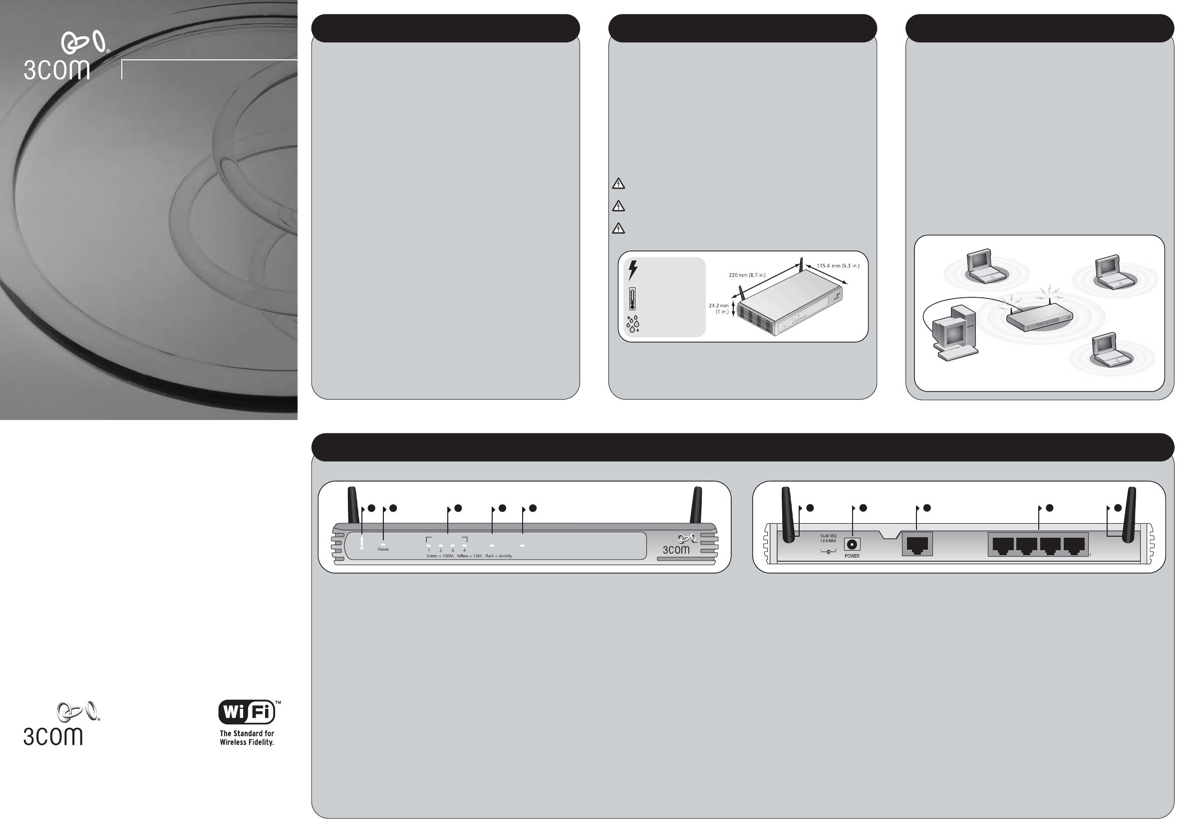
ABOUT YOUR GATEWAY
21 3 4
OfficeConnect Wireless 11b Cable/DSL Gateway
3CRWE53172
LAN Status Cable/DSL
5
WLAN
Alert
7 8 9
4
Ethernet
Cable/
DSL
6 6
LAN
4Wireless LAN (WLAN) Status LED (yellow)
If the LED is on it indicates that wireless networking is
enabled. If the LED is flashing, the link is OK and data is
being transmitted or received. If the LED is off, the
Wireless LAN has been disabled in the Gateway, or there
is a problem (refer to the User Guide).
5 Cable/DSL Status LED
green (100Mbps link) / yellow (10Mbps link)
If the LED is on, the link between the Gateway and the
cable or DSL modem is OK. If the LED is flashing, the link
is OK and data is being transmitted or received. If the LED
is off, nothing is connected, the modem is switched off
or there is a problem (refer to the "Problem Solving"
section).
6Wireless Antennae
The antennae on the product should be placed in a ‘V’
position when initially installed.
7 Power Adapter socket
Only use the power adapter that is supplied with this
Gateway. Do not use any other adapter.
8 Ethernet Cable/DSL port
The Ethernet Cable/DSL port is configured as MDI, for
connection to your modem with the supplied straight-
through patch cable. The port will automatically adjust
to the correct speed and duplex.
9 Four 10/100 LAN ports
Using suitable RJ45 cable, you can connect your
Gateway to a computer, or to any other piece of
equipment that has an Ethernet connection (for
example, a hub or a switch). The LAN ports are
configured as MDIX, for connection to a computer with
a straight through RJ-45 cable.
1 Alert LED (orange)
Indicates a number of different conditions, as described
below.
Off - The Gateway is operating normally.
Flashing quickly - Indicates one of the following
conditions:
• The Gateway has just been started up and is
running a self-test routine, or
• The administrator has invoked the Reset to Factory
Defaults command, or
• The system software is in the process of being
upgraded
In each of these cases, wait until the Gateway has
completed the current operation and the alert LED
is Off.
Flashing slowly - The Gateway has completed the Reset
to Factory Defaults process, and is waiting for you to
reset the unit. To do this, remove power, wait 10 seconds
and then re-apply power. The Gateway will then enter
the start-up sequence and resume normal operation.
On for 2 seconds, and then off - The Gateway has
detected and prevented a hacker from attacking your
network from the Internet.
Continuously on - A fault has been detected with your
Gateway during the start-up process. Refer to the main
User Guide.
2 Power LED (green)
Indicates that the Gateway is powered on.
3 Four LAN Status LEDs
green (100Mbps link) / yellow (10Mbps link)
If the LED is on, the link between the port and the next
piece of network equipment is OK. If the LED is flashing,
the link is OK and data is being transmitted or received. If
the LED is off, nothing is connected, or the connected
device is switched off, or there is a problem with the
connection (refer to the "Problem Solving" section). The
port will automatically adjust to the correct speed and
duplex.
Wireless 11b Cable/DSL Gateway - Front Wireless 11b Cable/DSL Gateway - Rear