


Hardware
80 Megabit Modem 410F and 420F User Manual
Connector Pinouts
You may choose to make your own cables for the ADSL RJ-11 connector and the
10/100BASE-T Ethernet connector on the rear of the modem. The following sections provide
the pinout information you need.
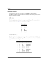
ADSL Port
The following table shows the signal on each pin for the ADSL port. The connector for this
interface is an RJ-11. See page 14 for the location of this port.
10/100BASE-T Port
The following table shows the signal on each pin when the switch is in either the MDI or the
MDI-X position for the 10/100BASE-T port. The connector for this interface is an RJ-45. See
page 14 forthelocationofthisport.
Pin Signal
1 Not used
2 Not used
3Ring
4Tip
5 Not used
6 Not used
MDI MDI-X Signal Description
1 3 TX+ Transmit Data (+)
2 6 TX- Transmit Data (-)
3 1 RD+ Receive Data (+)
4 4 Not used Not used
5 5 Not used Not used
6 2 RD- Receive Data (-)
7 7 Not used Not used
8 8 Not used Not used