


ADCP-96-015 • Issue 1 • July 2004
Page 5
© 2004, ADC Telecommunications, Inc.
2 BEFORE STARTING THE INSTALLATION
This section provides general installation considerations, unpacking and inspection procedures,
and lists the tools and materials required for cabinet installation.
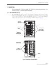
2.1 Installation Overview
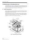
Installation of the ACE-142S/142V cabinet involves the following main tasks:
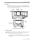
Installing a Support Base–The cabinet must be mounted on a suitable support base. The
following two mounting options are available:
• Fiberglass Mounting Sleeve (FMS)–The FMS provides a stable mounting platform plus
storage space under the cabinet for OSP cable slack. The FMS may also be used as a
splicing vault for the OSP feeder and distribution cables.
• Poured Concrete Pad–Concrete slab with Pad Mounting Frame (PMF). The PMF
provides a stainless-steel frame for mounting the cabinet. The PMF ensures that the
cabinet will be securely anchored to the concrete slab.
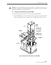
Mounting the Cabinet–After the support base is installed, the cabinet is secured to the support
base.
Feeder and Distribution Cable Installation–The cabinet OSP feeder and distribution cables
are routed into the cabinet and spliced.
Connector Panel Installation-Additional connector panels are installed in the cabinet if
needed.
Splitter installation–Additional splitters are installed in the cabinet if needed.
2.2 Unpacking and Inspection
This section provides instructions for opening the shipping boxes, verifying that all parts have
been received, and verifying that no shipping damage has occurred.
Use the following procedure to unpack and inspect the cabinet and all accessories:
1. Open the shipping carton(s) and carefully unpack the cabinet and any accessories from the
protective packing material.
2. Open the cabinet doors (requires 216B key tool) and check for broken or missing parts. If
there are damages, contact ADC (see Section 13) for an RMA (Return Material
Authorization) and to reorder if replacement is required.