


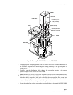

ADCP-96-015 • Issue 1 • July 2004
Page 9
© 2004, ADC Telecommunications, Inc.
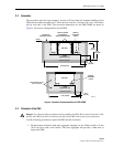
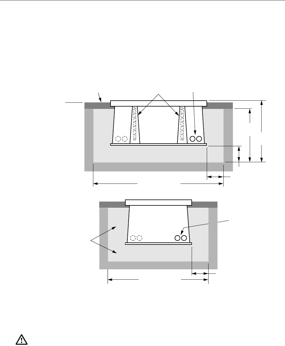
3.2 Excavation
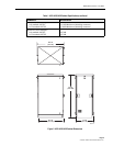
The excavation must be large enough to provide a fill base that will maintain stability for the
FMS and the cabinet mounted on it. There must be room for 12 inches (30.5 cm) of fill below
and on each side of the FMS. The excavation dimensions for the FMS 20000 are shown in
Figure 4. Excavate a rectangular hole for the FMS.
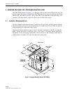
Figure 4. Excavation Recommendations for FMS-20000
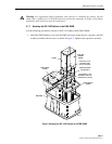
3.3 Placement of the FMS
Use the following procedures to place the FMS into the excavation.
1. Fill the bottom of the hole with stone aggregate, tamping it as it is filled to build a 12 inch
(30.5 cm) layer with a level surface. The stone aggregate will provide a stable base to
support the FMS.
Danger: Use adequate lifting equipment when installing the FMS. Do not stand in the hole while
placing the FMS in position. An unexpected shift of the FMS could result in personal injury.
19090-B
SIDE VIEW
92 IN (234 CM)
END VIEW
71 IN (180 CM)
TOPSOIL OR
DECORATIVE ROCK
STONE
AGGREGATE FILL
STONE
AGGREGATE FILL
42 IN
(106.7 CM)
12 IN
(30.5 CM)
12 IN
(30.5 CM)
CONDUIT
ENTRANCE
HOLES
CONDUIT
ENTRANCE
HOLES
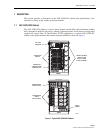
VERTICAL RACKS
FOR MANHOLE
CABLE SUPPORT BARS.
COMPACTED SOIL
38 IN
(96.5 IN)
COMPACTED SOIL
TAMP AGGREGATE AS
HOLE IS FILLED
GRADE