


ADCP-96-015 • Issue 1 • July 2004
Page 13
© 2004, ADC Telecommunications, Inc.
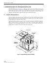
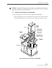
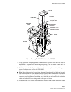
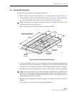
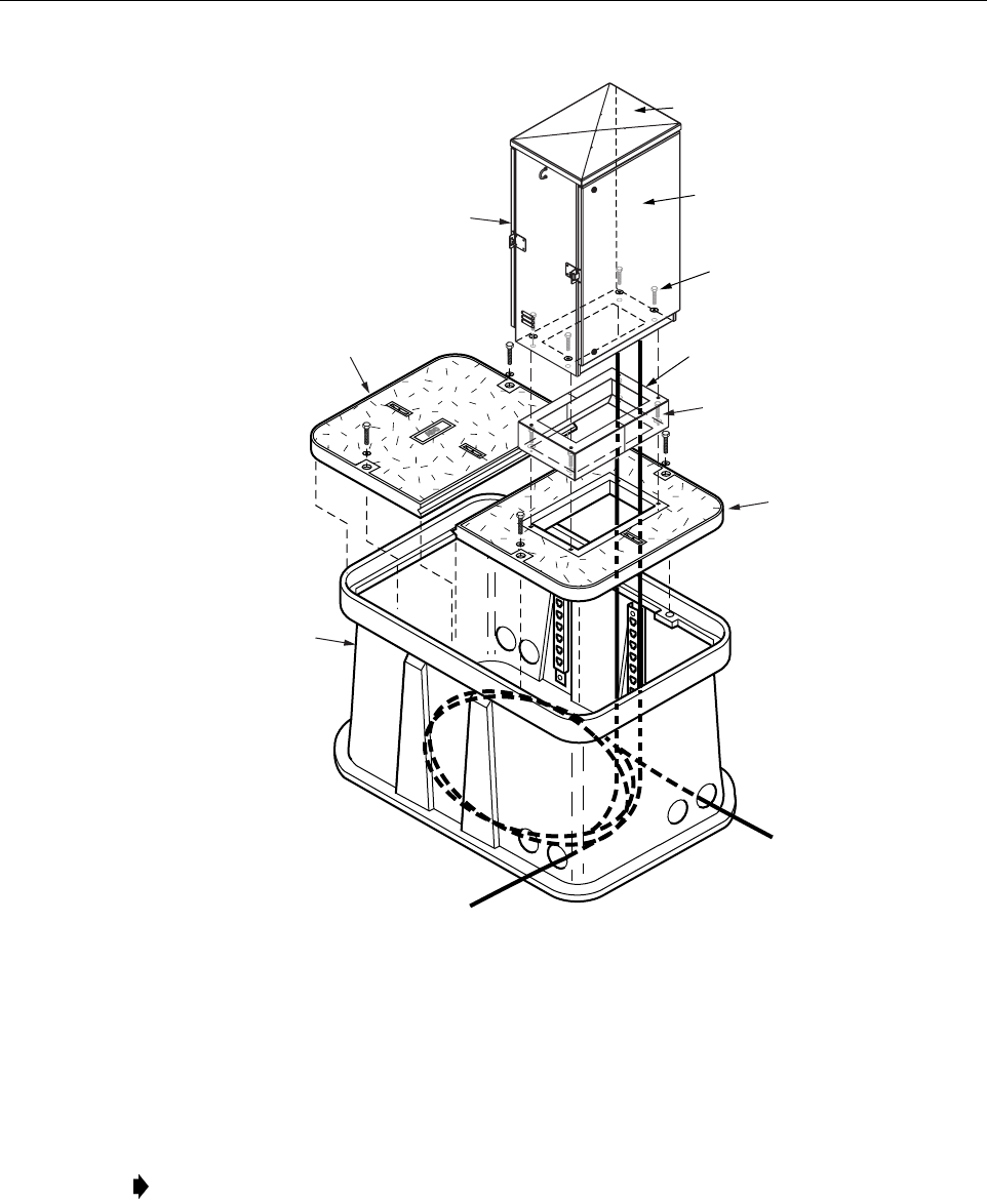
Figure 6. Mounting The ACE-142V Cabinet on the FMS-20000
7. Using appropriate lifting equipment, hold the cabinet in position over the FMS-20000 so
the cabinet is suspended over the rectangular opening in the top of the ground spacer or
adapter cover.
8. Carefully route the distribution cables through the rectangular opening in the ground
spacer or adapter cover and into the FMS-20000.
9. Locate the ends of the conduit sections that were installed in the bottom of the FMS-20000.
Note: The cables are coiled on spools for shipment. On each spool is a label that lists each
fiber subunit within the cable and the connector panels where each subunit is terminated.
After the cable is unspooled, label each cable with the corresponding fiber subunit and
connector panel designations. In addition, tag or label the stub end of each cable so that the
cable can be identified after being routed to the splice enclosure.
FMS SLEEVE
COVER
FMS ADAPTER
COVER
FMS-20000
19814-A
ACE-142V
CABINET
FRONT SIDE
HEX BOLTS, FLAT
WASHERS, AND
NUTS (4 PLACES)
CAPSCREWS, LOCK
WASHERS, AND FLAT
WASHERS (4 PLACES)
REAR SIDE
GROUND SPACER
(ACCESSORY)