


ADCP-96-015 • Issue 1 • July 2004
Page 22
© 2004, ADC Telecommunications, Inc.
5 FEEDER CABLE INSTALLATION AND SPLICING
This section describes how to install the OSP feeder cables in the ACE-142S/142V cabinet and
how to use the feeder cable splice trays.
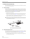
5.1 Bottom Cover Removal
The ACE-142S/142V cabinet is equipped with a two-piece bottom cover that prevents moisture
and dirt from entering the cabinet through the bottom. The cable-entry section of the bottom
cover must be removed to allow installation of the OSP cables. If the bottom cover was removed
previously, skip this section and proceed to Section 5.2. Use the following procedure to remove
the cable-entry section of the cabinet bottom cover from the cabinet:
1. Open the rear door of the cabinet.
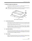
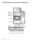
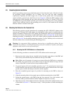
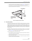
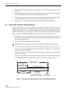
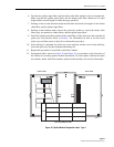
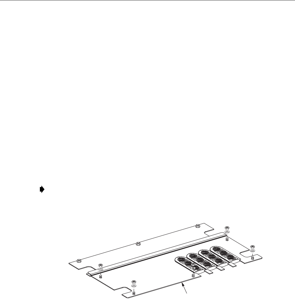
2. Remove the five lock nuts and five flat washers that secure the cable-entry section of the
bottom cover to the cabinet as shown in Figure 12. Save the nuts and washers for reuse.
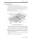
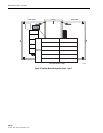
3. Lift up the cable-entry section of the bottom cover and push it toward the front of the
cabinet so it will be out of the way when the OSP cables are installed.
Figure 12. Bottom Cover Cable-Entry Section Removal
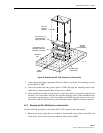
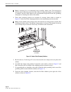
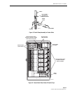
5.2 Cabinet Grounding Wire Connection
Prior to mounting the cabinet, a grounding system should have been installed and a grounding
wire should have been connected to the grounding system (see Section 3.5 or Section 4.5). Use
the following procedure to attached the grounding wire to the cabinet grounding lug:
1. Locate the grounding wire that was installed prior to mounting the cabinet and pull several
feet of slack up and into the cabinet.
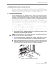
Note: Be careful not to damage the gaskets that are attached to the underside of the bottom
cover. If the distribution cables are pre-installed, the gromments may be left in place over
the cables when the cover is removed.
19608-A
REMOVE BACK SECTION
OF BOTTOM COVER