


ADCP-96-015 • Issue 1 • July 2004
Page 23
© 2004, ADC Telecommunications, Inc.
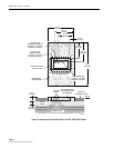
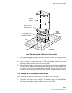
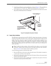
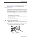
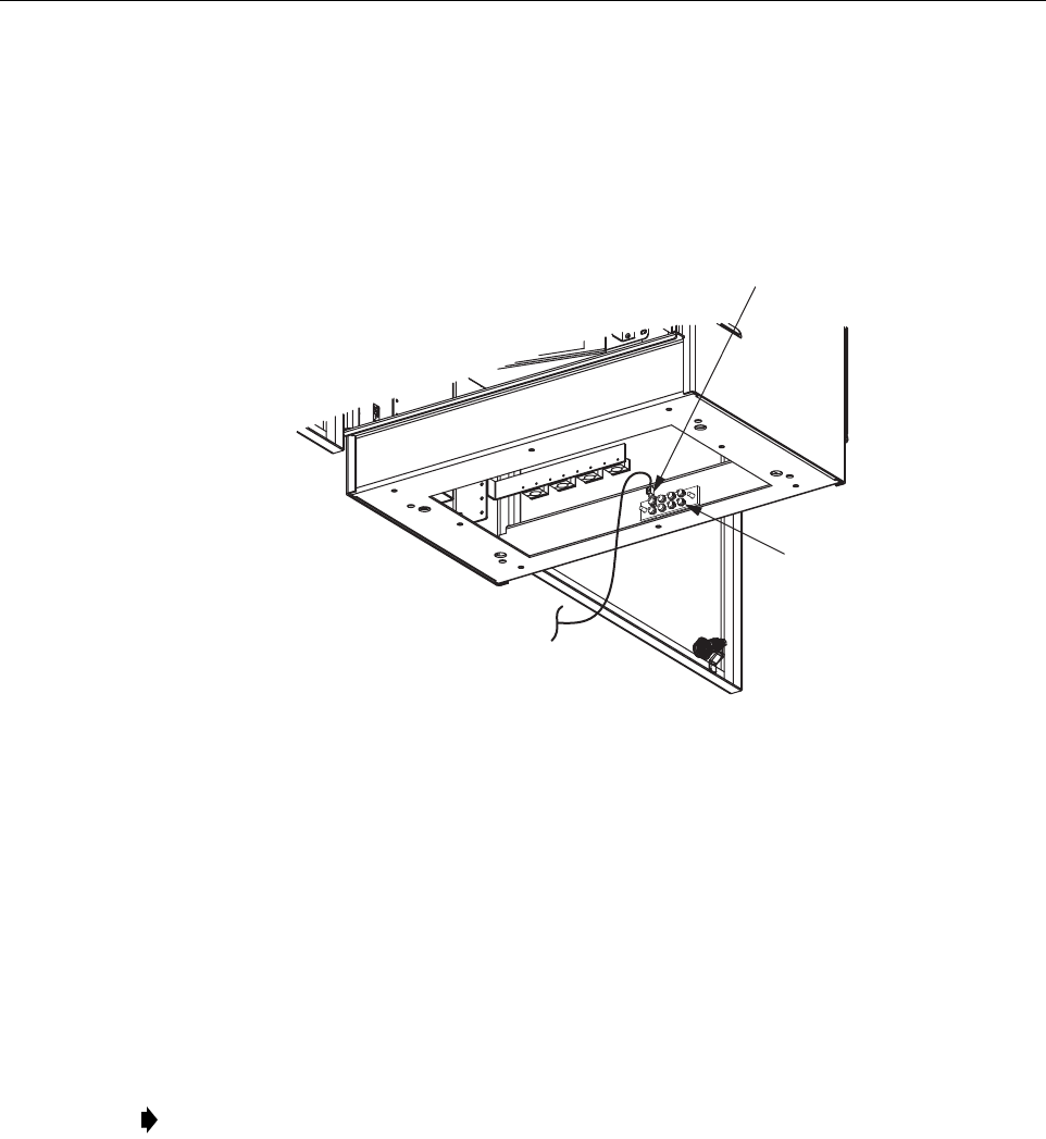
2. Attach the grounding wire to the grounding lug as shown in Figure 13. The grounding lug
can be used for #6 – #14 AWG wire. Tighten the grounding lug set screw securely.
3. Leave sufficient slack so the grounding wire can be repositioned as needed when the cable
entry section of the bottom cover is re-installed.
Figure 13. Grounding Wire Connection To Cabinet
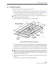
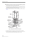
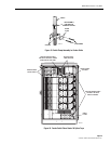
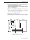
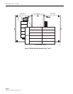
5.3 Feeder Cable Installation
The OSP feeder cable enters/exits the ACE-142S/142V cabinet from the bottom. At the entry/
exit point to the cabinet, the feeder cable is secured with a clamp. Beyond the clamp, the outer
sheath of the cable is removed to expose the optical fibers. The feeder cable is typically a 12- to
24-fiber cable with stranded or ribbon type fiber construction. Moisture blocking and/or
grounding kits should be installed (as required by local practice) to protect the exposed optical
fibers. From the clamping point, the optical fibers are routed to splice trays for splicing to the
splitter input fibers.
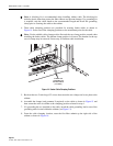
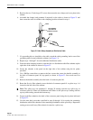
Use the following procedure to install the feeder cable:
1. Route the OSP feeder cable into the cabinet from the bottom. If the cabinet is mounted on
a concrete pad, use the duct on the right side.
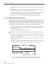
2. Pull the cable up through the cabinet and strip off 156 inches (396 cm) of the outside cable
sheath to expose the fiber subunits.
3. Install moisture-blocking and/or grounding kits as required by local practice. Follow the
installation instructions provided with each kit.
Note: If additional splitter modules will be installed in the cabinet as part of the initial
installation, complete splitter installation before proceeding with feeder cable installation.
Refer to Section 10 for the splitter module installation procedure.
CABINET GROUNDING LUG
(#6 - #14 AWG WIRE)
GROUNDING
STUDS FOR
OSP CABLES
WITH METALIC
ELEMENTS
NOTE: SHOWN WITH BOTH
THE FRONT AND REAR
SECTIONS OF THE BOTTOM
COVER (MOISTURE BARRIER)
REMOVED.
19610-A