


ADCP-96-015 • Issue 1 • July 2004
Page 24
© 2004, ADC Telecommunications, Inc.
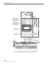
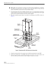
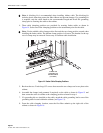
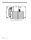
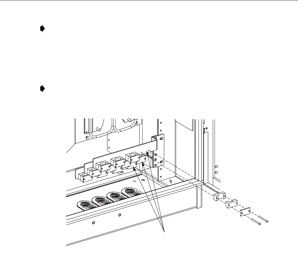
4. Three cable clamping positions are provided for securing feeder cables as shown in
Figure 14. Select one of the clamping positions as the attachment point for the cable.
Figure 14. Feeder Cable Clamping Positions
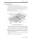
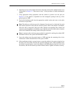
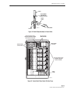
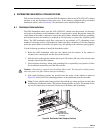
5. Back out the two 2-inch long 6-32 screws that secure the two clamps and cover plate to the
cabinet.
6. Assemble the clamps (and grommet if required) on the cable as shown in Figure 15 and
then secure the cable to cabinet at the clamping position selected in step 4.
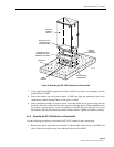
7. If a grounding kit was installed on the cable, attach the cable grounding lead to one of the
grounding studs located within the cabinet (see Figure 13).
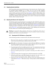
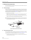
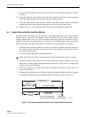
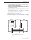
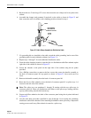
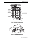
8. From the cable clamping location, route the first fiber subunit up the right side of the
cabinet as shown in Figure 16.
Note: A blocking kit is recommended when installing ribbon cable. The blocking kit
includes plastic tubes that protect the fiber ribbons and prevent damage. If a grounding kit
is required, strip the cable sheath to the recommended length and install the grounding
clamp prior to securing the cable to the cabinet.
Note: Use the middle cable clamp position first and the top clamp position second when
installing the feeder cables. The bottom clamp position is an extra. The bracket for the top
row of clamps may be removed if necessary to facilitate cable installation.
19740-A
CLAMPS FOR
ATTACHING THE
FEEDER CABLES
(3 PLACES)