


ADCP-96-015 • Issue 1 • July 2004
Page 26
© 2004, ADC Telecommunications, Inc.
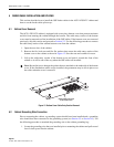
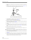
9. Secure the fiber subunit to the panel on the right side of the cabinet using the tie points
provided.
10. From the right side of the cabinet, route the fiber subunit to the center panel located just
below the splitter modules and secure using the tie point provided.
11. From the center panel, route the fiber subunit to the splice wheel used for the splitter
module input fibers following the same path as the splitter module input fibers.
12. Repeat steps 1–11 for each feeder cable subunit and each additional feeder cable.
5.4 Feeder Cable and Splitter Input Fiber Splicing
The OSP feeder cable fibers must be spliced to the splitter input fibers. Up to twelve splitter
modules may be mounted in the cabinet so that a maximum of twelve feeder splices may be
required. Round splice trays are used for splicing and seven splice tray mounting slots are
provided. Each splice tray can hold up to 12 splices. Use the following procedure to install the
feeder cable fibers and splitter input fibers in each splice tray in preparation for splicing:
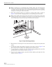
1. The input fibers from each splitter are routed to a splice tray located on the top left side of
the cabinet. Locate the splice tray that was used for the splitter input fibers and remove
that tray from the cabinet.
2. Uncoil the splitter input fibers from the splice tray.
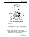
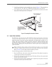
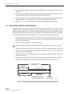
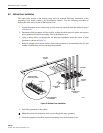
3. Secure the splitter input fibers and the feeder cable fiber subunit together at the point
where the two come together before entering the splice tray (see Figure 16). Adjust slack
as necessary to prevent binding.
4. Check the routing of the splitter input fibers and adjust as needed to relieve tension or
remove excess slack.
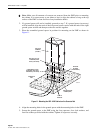
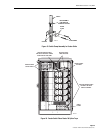
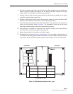
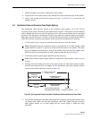
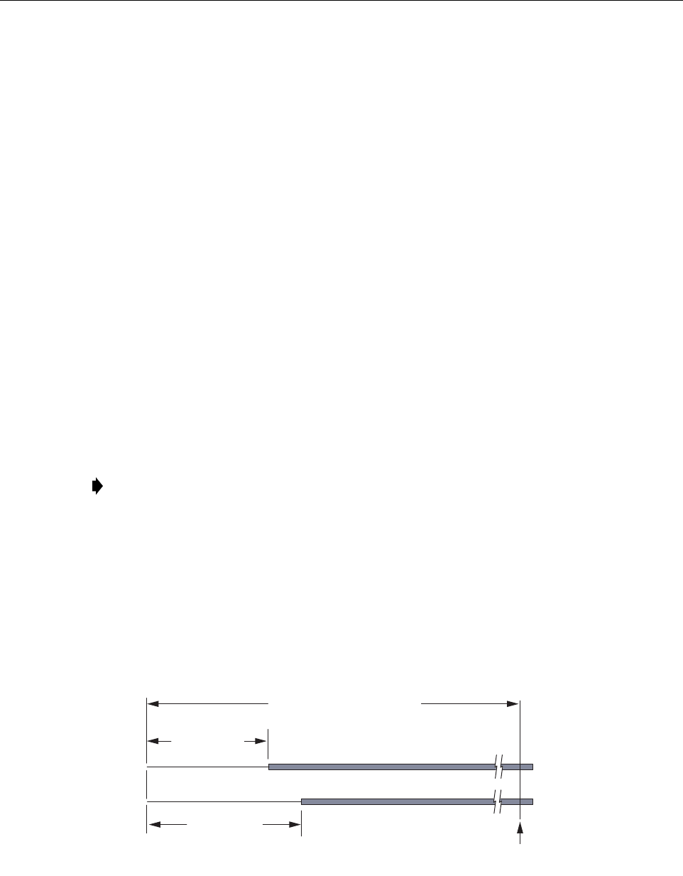
5. Starting at the common tie point within the cabinet, measure and mark the fiber cut lengths
for the splitter input fibers and the feeder cable fiber subunits as shown in Figure 17.
Figure 17. Cut Length and Breakout Length for Feeder Cable and Splitter Input Fiber
Note: The splitter input fibers are temporarily coiled around the splice tray for storage.
COMMON TIE
POINT IN CABINET
19220-A
BREAKOUT
LENGTH 48 IN
(122 CM)
BREAKOUT
LENGTH 37 IN
(94 CM)
CUT LENGTH* 68 TO 146 IN
(173 TO 371 CM)
FEEDER CABLE
FIBER SUBUNIT
SPLITTER INPUT FIBER
*THE CUT LENGTH MUST BE
THE SAME FOR BOTH FIBERS