


ADCP-96-015 • Issue 1 • July 2004
Page 37
© 2004, ADC Telecommunications, Inc.
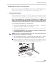
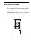
7 GUIDELINES FOR USING ROUND SPLICE TRAYS
This section provides guidelines for using the round splice trays that are provided with the
ACE-142S/142V cabinet. Use the following procedure for installing the fibers in the tray:
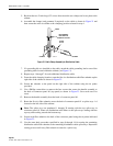
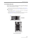
1. Remove the top and bottom covers from the splice tray.
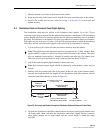
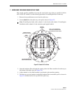
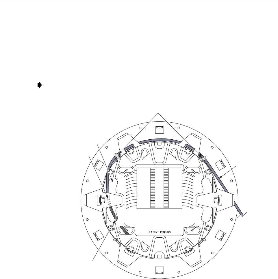
2. Secure subunit A to the splice tray at the points shown in Figure 29.
Figure 29. Subunit A Tie Points
3. Insert the breakout fibers through the opening where the fibers transition from the top to
the bottom of the splice tray (see Figure 29).
4. Adjust subunit A so the fiber breakout is positioned at the transition opening.
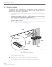
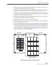
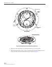
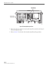
5. Turn the tray over and continue routing the breakout fibers around the spools as shown in
Figure 30 and then back to the top side of the splice tray.
Note: If installing the feeder cable, subunit A is the feeder cable subunit. If installing the
distribution cable, subunit A is the connector panel pigtail subunit.
SUBUNIT A
(SEE NOTE 1)
SUBUNIT A
TIE POINTS
TRANSITION POINT
FROM TOP TO BOTTOM
TOP SIDE
FIBER
BREAKOUT
POINT
STRANDED/RIBBON FIBER
(ROUTE TO BOTTOM SIDE)
19280-A
NOTE 1: FOLLOW SUBUNIT A
ROUTING FOR FEEDER CABLE
OR CONNECTOR PANEL FIBERS