


ADCP-96-015 • Issue 1 • July 2004
Page 38
© 2004, ADC Telecommunications, Inc.
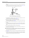
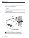
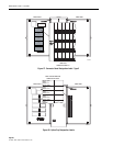
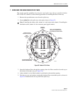
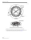
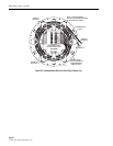
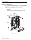
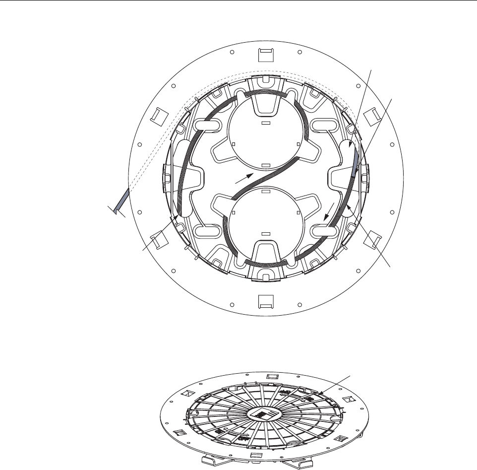
Figure 30. Routing Subunit A Around Back Side of Splice Tray
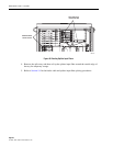
6. Replace the splice tray bottom cover and then turn the tray over to the top side.
7. Route the breakout fibers at least 1.5 times around the inside of the tray making the loop as
large as possible to ensure maximum fiber storage as shown in Figure 31.
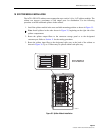
AFTER ROUTING CABLES,
REPLACE BOTTOM COVER
TRANSITION POINT
ROUTE TO
TOP SIDE
STRANDED/RIBBON
FIBERS
BOTTOM SIDE
FIBER
BREAKOUT
POINT
19229-A