


ADCP-96-015 • Issue 1 • July 2004
Page 43
© 2004, ADC Telecommunications, Inc.
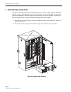
10 SPLITTER MODULE INSTALLATION
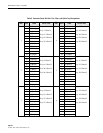
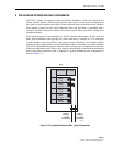
The ACE-142S/142V cabinet can accommodate up to twelve 1x8 or 1x32 splitter modules. The
cabinet can support a maximum of 360 output ports for distribution. Use the following
procedure to install additional splitters in the cabinet:
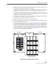
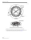
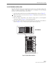
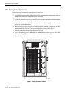
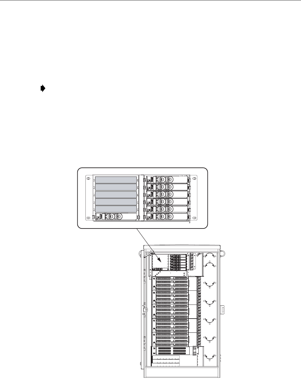
1. Install the splitter module in the next available mounting position as shown in Figure 35.
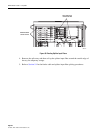
2. Route the splitter output fibers to the connector storage panel or to the designated
customer port. Refer to Section 11 for the routing procedure.
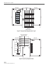
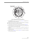
3. Route the splitter input fiber to the designated splice tray at the back of the cabinet as
shown in Figure 36. Up to 12 fibers may be spliced within each splice tray.
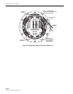
Figure 35. Splitter Module Installation
Note: Install splitters in the order shown in Figure 35, beginning on the right side of the
splitter compartment.
19636-A
1
2
3
4
5
6
7
8
9
10
11
12
DETAIL DRAWING OF
SPLITTER MODULES