ADCP-75-169 • Issue 1 • June 2004
Page 1
© 2004, ADC Telecommunications, Inc.
1 INTRODUCTION
The rear access Host Unit serves as the EBTS servicing unit for the Digivance LRCS system. A
typical LRCS system consists of a Host Unit (HU) and a Remote Unit (RU). The HU consists of
an electronic chassis assembly that mounts in a standard equipment rack. The RU consists of
multiple electronic and optical modules that mount in either an outdoor cabinet or an indoor
mounting shelf. The HU and the RU together comprise an LRCS system. Various accessory
items are also available for use with the basic LRCS system. All items referenced as “accessory
items” are not furnished with the basic system and must be purchased separately.
2 HOST UNIT DESCRIPTION
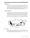
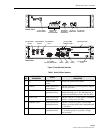
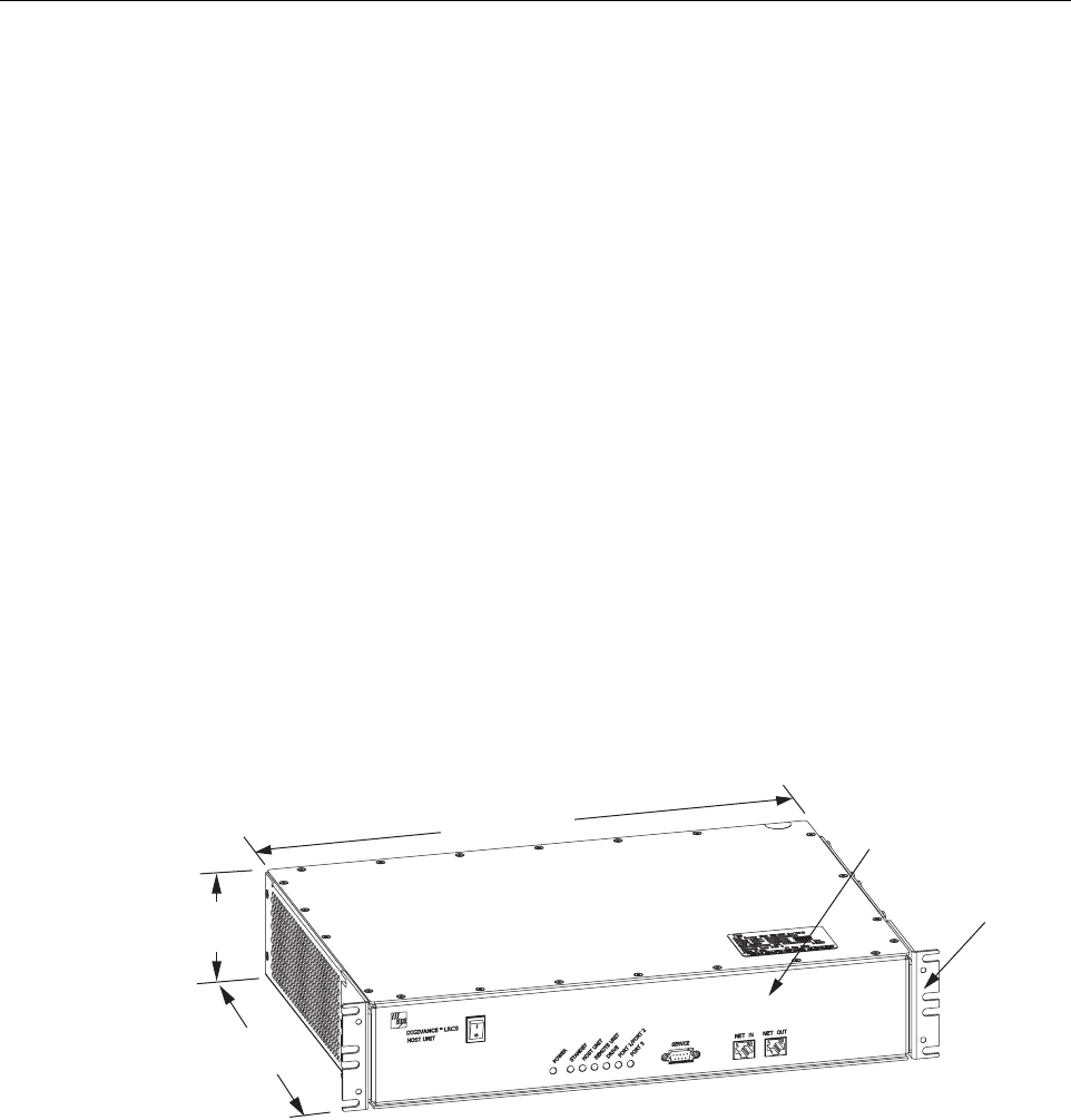
The HU, shown in Figure 1, consists of an electronic circuit board assembly and a fan assembly
that are mounted within a powder-paint coated sheet metal enclosure. The enclosure provides a
mounting point for the circuit board and fan assemblies and controls RF emissions. The only
user-replaceable component is the fan assembly. The HU is designed for use within a non-
condensing indoor environment such as inside a wiring closet or cabinet. The RF connectors,
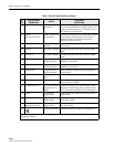
optical connectors, alarm output connectors, DC power terminal strip, and grounding lug are
mounted on the HU rear side. The On/Off power switch, LED indicators, service interface
connector, and Controller Area Network (CAN) connectors are mounted on the HU front panel.
Figure 1. Host Unit
2.1 Mounting
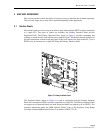
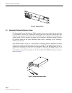
The HU is intended for rack-mount applications. A pair of reversible mounting brackets is
provided that allow the HU to be mounted in either a 19-inch or 23-inch EIA or WECO
equipment rack. When installed, the front panel of the HU is flush with the front of the rack.
Screws are provided for securing the HU to the equipment rack.
17.1 INCHES
(433 mm)
3.5 INCHES
(88 mm)
12.2 INCHES
(311 mm)
FRONT PANEL
MOUNTING
BRACKET
(BOTH SIDES)
17857-A


