


Chapter 1: Overview September 25, 2006
1-2 LTPE-UM-3159-02
FRONT PANEL
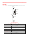
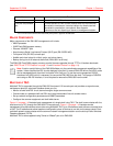
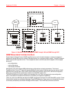
Figure 1-1 and Table 1-1 identify and describe the front-panel components of the EMU-830 Lists 4A and 6A.
Figure 1-1. EMU-830 Front Panel
Table 1-1. EMU-830 List 4A and 6A Front Panel Components
Name Mode Function
System Status LEDs:
Power Green Indicates power to the EMU-830.
Fail Red
Indicates system failure.
a
EXT Comm Green Indicates when data is being transmitted from the EMU-830
console port to a management station.
Alarm LEDs:
Critical ALM Red Indicates a critical alarm condition.
Major ALM Yellow Indicates a major alarm condition.
Minor ALM Yellow Indicates a minor alarm condition.
Alarm Cut-off LED and Switch:
ACO LED Green Indicates the Alarm Cut-Off (ACO) was activated.
ACO switch On/Off Activates ACO from the front panel if an alarm is active.
POWER
FAIL
EXT COMM
CRITICAL
MAJOR
MINOR
ALM
ACO
RESET
V.24
EMU-830
Reset switch
V.24 (RS-232) console por
t
Alarm cut-off LED
and switch
Alarm LEDs
System status LEDs