C A U T I O N !
SUBJECT TO ELECTROSTATIC DAMAGE
OR DECREASE IN RELIABILITY.
HANDLING PRECAUTIONS REQUIRED.
For more information, refer to the Installation and Maintenance Practice (P/N 61181107L1-5) available online at www.adtran.com.
©2007 ADTRAN, Inc.
All Rights Reserved.
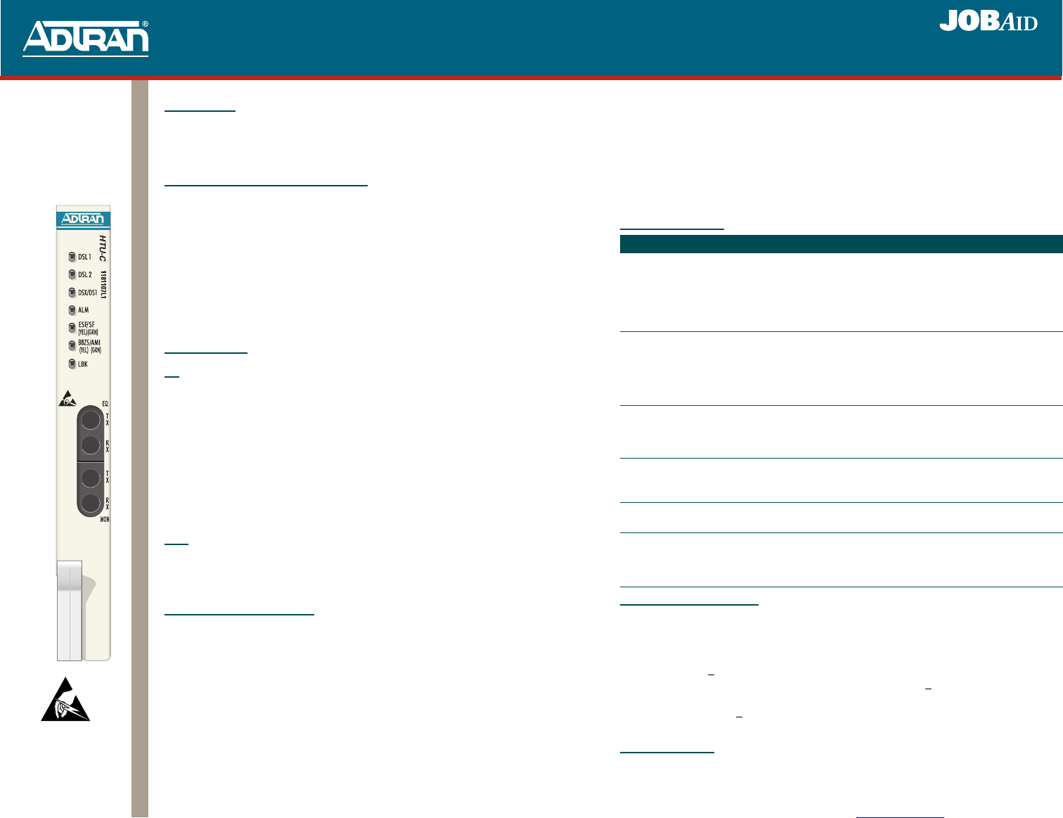
Total Access 3000/3010
HTU-C
P/N: 1181107L1
CLEI: T1I3AAEA_ _
3. Hold the HTU-C by the front panel while supporting the bottom edge of the module with the
ejector latches opened to engage the chassis edges.
4. Align the module edges to fit in the lower and upper guide grooves for the module.
5. Slide the HTU-C into the access module slot. Apply simultaneous thumb pressure at the top
and bottom of the module (to the right of the ejector latches) to ensure that the module is
firmly seated against the chassis backplane connector. Secure the HTU-C in place by rotating
the ejector latch into the locked position.
After installation is complete, the HTU-C performs a series of initialization and self-tests. Once the
series of self-tests are completed, the front panel LEDs reflect the true state of the hardware.
FRONT PANEL LEDS
HDSL DEPLOYMENT GUIDE
The HDSL system is designed to provide DS1-based service over loops as follows:
♦ Cable pairs must be non-loaded
♦ No single bridged tap > 2 kft (0.61 meters)
♦ Impulse noises < 50 dB as measured using a 50 kB filter
♦ Wideband noise < 31 dBrn as measured using a 50 kB filter
♦ Pulse attenuation (LOSS on HDSL current system status screen) < 30 dB
♦ Total bridged tap < 2.5 kft (0.76 meters)
♦ 196 kHz insertion loss < 35 dB
♦ Maximum loop resistance is 800 ohms
OPTION SETTINGS
The table on the following page lists options that are available when configuring the HTU-C.
However, some options are pre-set and dependent upon the System Controller Unit (SCU) being
used. Refer the appropriate SCU Installation and Maintenance Practice when setting options.
Label Status Description
DSL1/
DSL2
{
z
z
z
5
Off
Green
Yellow
Red
Flashing
No synchronization of HTU-C and HTU-R on either loop
Good signal quality (4 to 9) on Loops 1 and 2
Signal quality marginal (1 to 3) on Loops 1 and 2
Signal quality poor (0) on Loops 1 and 2
Error detected at HTU-C or HTU-R. The color of the LED, when
flashing, indicates loop signal quality.
DSX/DS1
{
z
✷
Off
Green
Green Flashing
Network-side DSX-1 signal not detected or of a format that does not
match provisioning of HDSL circuit
Network-side DSX-1 signal is present and synchronized with the
HTU-C’s interface
Bipolar Violation (BVPV), frame bit error (SF mode), or CRC error
(ESF mode) detected at DSX-1 signal
ALM
{
z
z
Off
Yellow
Red
No alarm condition detected
Remote alarm condition (HTU-C) detected
Alarm condition detected either locally (HTU-C), or locally and
remotely (HTU-C and HTU-R)
ESF/SF
{
z
z
Off
Green
Yellow
Unit is receiving Unframed data
Unit is receiving SF data
Unit is receiving ESF data
B8ZS/AMI
z
z
Green
Yellow
Unit is receiving AMI coding
Unit is receiving B8ZS coding
LBK
{
z
✷
Off
Yellow
Yellow Flashing
Unit is not in loopback or armed state
Local (HTU-C) loopback is active to the network
Loopback arming sequence has been detected; unit is armed (ready for
loopback) but not in loopback
DESCRIPTION
The Total Access 3000/3010 High-bit rate Digital Subscriber Line (HDSL) Transceiver Unit for
Central Office (HTU-C, P/N 1181107L1) is used to deploy an HDSL T1 circuit using 4-wire
metallic facilities. The HTU-C works with multiple list versions of the HDSL Unit Remote end
(HTU-R) and HDSL Range Extenders (HRE).
MENU ITEMS ACCESSIBLE VIA THE SCU
Local or remote craft port access to the Total Access 3000 HTU-C can be provisioned and tested
through the System Controller Unit (SCU). When deployed with SCU 1181015L1 or
1181017L1, the HTU-C can be provisioned via the SCU’s faceplate Four Character Display.
Refer to the Total Access 3000 System Controller Unit (SCU) Installation and Maintenance
Practice (P/N 61181017L1-5) for additional information.
Connect a terminal emulator via the RS-232 (DB-9) connector on the faceplate of the SCU. The
terminal must be VT100 or compatible and defaulted to 9600 bps, 8 bit, no parity, 1 stop bit. At
the LOGON screen, enter the system User Name and Password. Refer to the appropriate SCU
Job Aid for the default PASSWORD. Access the desired HRTU-C by selecting the ACCESS
MODULES from the Total Access Menu, and then select the corresponding slot number.
NOTE: When using a PC with terminal software, disable any power saving programs.
BANTAM JACKS
EQ
This jack provides an intrusive test access point to the data stream as follows:
♦ Equipment Jack = To Customer
♦ TX: Replaces the data stream being transmitted to the customer (HDSL Loops)
♦ RX: Accesses the data stream being received from the customer (HDSL Loops)
♦ Equipment jack = To Network
♦ TX: Replaces the data being transmitted to the Central Office
♦ RX: Access the data being received from the Central Office
When the HTU-C is in MUX mode, the EQ jack can be configured for “To Network” or “To
Customer” (default setting) direction via the Test screen. In DSX mode, this option is not
available, and the EQ jack configuration will be “Fixed to Customer.”
MON
This jack provides nonintrusive tap to monitor characteristics of the DSX signal as follows:
♦ TX: Monitors signal being transmitted to the customer (HDSL Loops)
♦ RX: Accesses the data being received from the customer (HDSL Loops)
INSTALLATION AND TURN-UP
After unpacking the unit, inspect it for damage. If damage is noted, file a claim with the carrier
and then contact ADTRAN. For more information, refer to the warranty.
NOTE: This unit can be provisioned via the RS-232 port or remotely via inband codes.
To avoid confusion with the access module and common module slots, the access
module slots start with the fourth slot from the left on the shelf and are numbered “1”
through “28” for the Total Access 3000, and “1” through “22” for the Total Access
3010 on the underlying silk-screen. Attempting to install the HTU-C in any other slots
other than those listed can damage the module, backplane or both.
To install the HTU-C, perform the following steps:
1. If present, remove the blank panel from the access module slot on the rear of the Total
Access 3000/3010 chassis that is intended for the HTU-C.
2. Pull the ejector latch, located on the bottom of the HTU-C front panel, from the closed
positions.
61181107L1-22A
0710
Total Access 3000/3010
HTU-C


