


Chapter 2. Installation and Operation
61200659L1-1 MX2800 User Manual 2-7
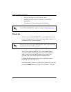
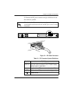
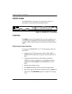
REAR PANEL
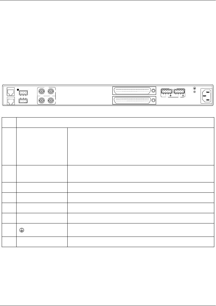
The MX2800 STS-1 rear panel is equipped with a LAN port, a
modem port, two alarm output terminal blocks, two sets of NET
in/out jacks, two Amphenol (Amp) connectors, and DC/AC power
connections. Figure 2-3 illustrates the rear panel and identifies its
equipment. Descriptions for these items follow the figure. Pin
assignments are given in Appendix A, Pinouts.
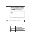
Figure 2-3. MX2800 STS-1 Rear View
L
A
N
1
2
3
4
M
O
D
E
M
CRITICAL
NOCOMNC
NONCRITICAL
IN
OUT
A
B
DSX-1/E1
(OUT)
DSX-1/E1
(IN)
USE COPPER
CONDUCTORS ONLY!
PWR
FAIL
RET
RET
PWR
FAIL
AB
DC POWER
115VAC 50/60HZ
0.8a
5
6
7
8
NET
#Item Function
1 LAN 10BaseT LAN connection
Note: The LED to the right of this connector illuminates
when the unit is connected to an active ethernet seg-
ment.
2 Modem Telephone line connection for internal V.34 modem (see
note on page 2-8)
3 Noncritical/Critical Connections for external audible/visible alarms
4 NET Network service connections for controller cards A and B
5 DSX-1/E1 64-pin Amp connectors for T1/E1s
6 Power DC power connection
7
Ground stud
8 115 VAC 50/60Hz AC power connection