


Chapter 2. Installation and Operation
61200659L1-1 MX2800 User Manual 2-9
rackmount units. Once a modular connector is wired, push it firmly
into the rear panel
NONCRITICAL
or
CRITICAL
connector.
The alarm functions can be enabled or disabled through the
A
LARM
R
ELAYS
section of the
C
ONFIGURATION
menu (see the section Alarm
Relays on page 3-18).
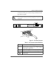
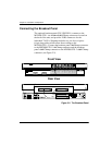
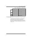
Network Interfaces
The network interfaces are full-duplex circuits provided by four
BNC coaxial cable connections (two for each controller card). The
receive data from the network is connected to the RX (
IN
)
connectors, while the transmit data from the MX2800 STS-1 is
connected to the TX (
OUT
) connectors.
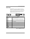
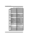
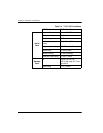
DSX-1/E1 Interfaces
The DSX-1/E1 interfaces are 64-pin Amp connectors. These
interfaces provide Tx and Rx connections between the unit and
equipment such as wire-wrap patch panels, punch-down panels, or
breakout panels.
Power Connection
The DC and AC power connections are described earlier in this
chapter on page 2-2.
Network interfaces must be connected using coaxial cables that have
the shields grounded at both ends.
Connect the DSX-1/E1 interfaces to intra-building wiring only.