


61200214L1-1 IQ Probe User Manual 107
Appendix A. Pinouts
Appendix A
Pinouts
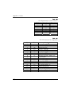
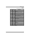
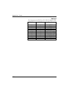
The following tables give the pin assignments for the IQ Probe
connectors, adapter cables, and card options. For more informa-
tion, see the chapter Installation.
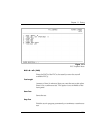
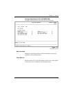
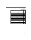
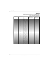
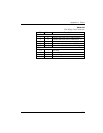
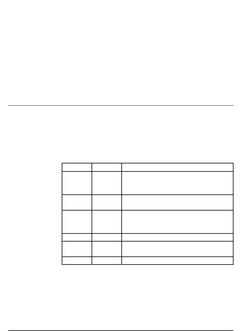
Table A-A
Pin Assignments for 10baseT Connector
Pin Name Description
1 TD+
The positive signal for the TD differential
pair. This signal contains the serial output
data stream transmitted onto the network.
2 TD-
The negative signal for the TD differential
pair (pins 1 and 2).
3 RD+
The positive signal for the RD differential
pair. This signal contains the serial input
data stream received from the network.
4, 5 N/A not used
6 RD-
The negative signal for the RD differential
pair (pins 3 and 6).
7, 8 N/A not used