


61200214L1-1 IQ Probe User Manual 49
Chapter 7. Configuring the DCE Port
Chapter 7
Configuring the DCE Port
DCE PORT
Access the DCE port menus by selecting DCE PORT from the
Configuration menu. Full menu trees for the DCE Configuration
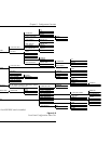
selections are shown in Figures 5-2 (Terminal Configuration Menu
Tre e) and 5-3 (Front Panel Configuration Menu Tree) of the Configu-
ration Overview chapter. The DCE port terminates the user end
of the frame relay UNI interface. The IQ Probe supports three
standard PVC signaling formats: LMI (gang of four), ANSI
T1.617-D (Annex D), and ITU Q.933-A (Annex A). The selected
signaling format is used to poll the DCE end of the UNI interface
and retrieve virtual circuit information. Optionally, the polling
process can be disabled.
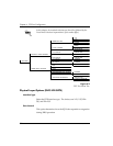
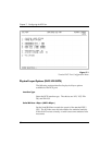
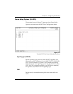
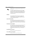
When configuring from a terminal, the screen in Figure
7-1 will appear when DCE Port is selected.
In this chapter, the terminal selections are listed first followed by the
Front Panel selections in parenthesis (if the names differ).