


TRACER 4106/4206 System Manual Section 2 Microwave Path Engineering Basics
612804206L2-1A © 2004 ADTRAN, Inc. 15
1. LINE-OF-SIGHT
The TRACER 4106 and 4206 systems are designed for operation in the license-free 2.400 to 2.4835 GHz
and 5.725 GHz to 5.850 GHz industrial, scientific and medical (ISM) bands, respectively. Radio wave
propagation in these bands exhibit microwave characteristics which are ideally suited for point-to-point,
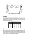
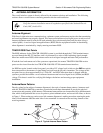
line-of-sight communications. Line-of-Sight requires that the transmitting antenna and receiving antenna
are able to “see” each other, and that the straight-line path between the two antennas is free of obstructions,
such as buildings, trees, mountains, and, in longer paths, even the curvature of the earth. In addition, for
maximum signal strength the area around the visual line-of-sight where microwave signals reflect (Fresnel
zone) must also be free of obstructions. Fresnel zones are discussed in more detail on page 22.
Terminology
2. DECIBELS
Understanding the decibel (dB) format is key when discussing microwave path engineering because the
received signal power is often expressed in decibel format. In general, any quantity can be expressed in
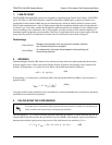
decibels. If the quantity x is a power level (in Watts), the decibel equivalent is defined as
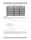
If the quantity x is referenced to a milliwatt (mW), then the decibel-milliwatt (dBm) is used instead of a
generic decibel.
Using the decibel format simplifies power calculations by reducing multiplication and division operations
into addition and subtraction operations.
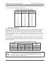
3. CALCULATING THE FADE MARGIN
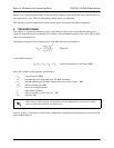
The fade margin (F ) is a value in decibels (dB) that represents the amount of signal reduction that can be
tolerated before the link exceeds the specified bit error rate (BER). Fade margin is simply the difference
between the available signal power at the receiver (P
R
) and the receiver sensitivity (P
sens
).
Point-to-Point
Wireless communication from a single site to another individual
site. Contrast with point-to-multipoint.
Line-of-Sight
An unobstructed, direct path exists between the transmitting and
the receiving antennas.
It is imperative to determine if the proposed microwave path is suitable (at a minimum) for
ideal, nondistorted signals before attempting installation.
x
dB
10 log
10
x()
⋅
=
(dB)
x
dBm
10 log
10
x
1mW
-------------
⋅
=
(dBm)
FP
R
P
sens
–=
(dB)
= P
T
+ G
T
+ G
R
- L - L
P
- P
sens