


TRACER 4106/4206 System Manual Section 2 Microwave Path Engineering Basics
612804206L2-1A © 2004 ADTRAN, Inc. 17
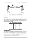
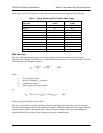
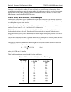
Figure 1. Example Microwave Path with Parameters
The following sections further discuss the power budget analysis and its components.
Antenna Gain
Actual transmit and receive antenna gain values depend strictly upon the physical characteristics of the
antennas installed for each link. In other words, the size of the dish determines the antenna gain. Using a
parabolic dish antenna results in the best performance. Antenna gains are specified in terms of decibels of
gain referenced to an isotropic source (dBi). An isotropic source is a hypothetical antenna having equal
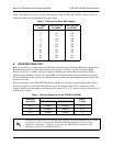
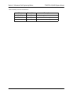
radiation in all directions. Typical antenna gains are listed in Table 1; however, dish manufacturers can
provide gains for specific types of antennas.
Transmitted Power (P
T
)
The FCC specifies the maximum transmitter power that may be used for antennae of a given gain. FCC
Rules Part 15, Subpart 247 allow for a maximum power of 1 Watt (30 dBm) into antennae of a gain less
than or equal to 6 dBi. At 2.4 GHz (TRACER 4106), the 1-watt maximum transmitter power must be
reduced by 1 dB for every 3 dB of antenna gain over 6 dBi. Since the TRACER 4106 maximum transmit
power is 100 milliwatts, only antennas with gains above 36 dBi (12-foot diameter parabolic dishes) require
any reduction in transmit power. For the 5.8 GHz band (TRACER 4206), there is no reduction in
transmitter output power required for antenna gains greater than 6 dBi.
Table 1. Antenna Gain for Given Dish Diameters
Dish Diameter
(in feet)
Gain at 2.4 GHz
(in dBi)
Gain at 5.8 GHz
(in dBi)
2 21 28.5
4 27 34.2
6 31 37.5
8 33 40.7
10 35 42.5
12 37 44.2
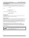
G
T
G
R
d, L
P
P
T
P
R
λ
L
L