


TRACER 4106/4206 System Manual Section 2 Microwave Path Engineering Basics
612804206L2-1A © 2004 ADTRAN, Inc. 19
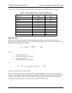
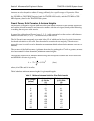
Table 2 gives typical loss figures for some of the more common coaxial cable types (per 100 feet).
Path Loss (L
P
)
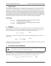
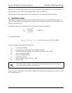
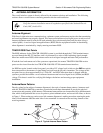
Path loss is the estimated attenuation between the transmit and receive antennas caused by signal
separation and scattering. The path loss is considered basic transmission loss over the microwave link. The
following expression calculates path loss:
where
f carrier frequency (Hz)
λ carrier wavelength (c / f) (meters)
d path distance (meters)
c speed of light, free-space (meters)
or
where d is expressed in miles and f in GHz
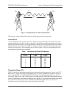
Path loss, as shown here, increases rapidly as either the path length increases or the carrier wavelength
decreases (which happens as the carrier frequency increases). Therefore, longer microwave paths naturally
experience more path loss than shorter paths. Likewise, higher frequency microwave communication
experiences more path loss than lower frequency microwave communication.
Table 2. Typical Coaxial Loss for Common Cable Types
Cable Type
2.4 GHz Loss/100 ft.
(in dB)
5.8 GHz Loss/100 ft.
(in dB)
RG58 80 N/A
RG8 (air) 20 N/A
RG8 (foam) 9 N/A
1/4” Coax 5.91 11.36
3/8” Coax 5.76 9.65
1/2” Coax 3.83 6.49
5/8” Coax 2.98 4.90
7/8” Coax 2.2 N/A
1 1/4” Coax 1.62 N/A
1 5/8” Coax 1.41 N/A
5.8 GHz Elliptical Waveguide N/A 1.23
L
P
4
π
d
λ
----------
2
4
π
df
c
------------
2
==
(dB)
L
P
96.6 20 log
10
d() 20·log+
10
f()
⋅
+=
(dB)