


Section 2 Microwave Path Engineering Basics TRACER 4106/4206 System Manual
20 © 2004 ADTRAN, Inc. 612804206L2-1A
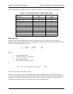
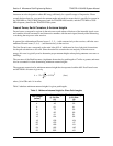
Table 3 lists path loss values for various path lengths for both 2.4 GHz and 5.8 GHz systems. Values not
listed in the table can be interpolated from those listed.
5. RECEIVER SENSITIVITY
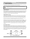
Receiver sensitivity is a value expressed in decibels referenced to one milliwatt (dBm) that corresponds to
the minimum amount of signal power needed at the receiver to achieve a given bit error rate (BER).
Receiver sensitivity is usually a negative number of decibels and smaller receiver sensitivity (higher
quantity negative number) is better for a given BER. Several factors affect receiver sensitivity including
the data bandwidth of the wireless link, and the amount of additional signal degradation introduced in the
receiver electronics.
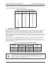
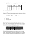
Receiver sensitivity of the TRACER 4106/4206 is dynamic as a function of desired bandwidth; receiver
sensitivity improves as delivered bandwidth decreases. In situations where 4xT1 connectivity is not
required, the delivered bandwidth can be decreased to either 2xT1 or 1xT1, and the receiver sensitivity will
be improved as follows:
Table 3. Path Loss for Given Path Lengths
Path Length
(miles)
Path Loss (dB)
at 2.4GHz
Path Loss (dB)
at 5.8 GHz
1104112
2110118
3114121
4116124
5118126
10 124 132
15 128 135
20 130 138
25 132 140
30 134 141
35 135 143
Table 4. Receiver Sensitivity for the TRACER 4106/4206
Delivered
Bandwidth
Receiver Sensitivity
Active
T1 Ports
TRACER 4106 TRACER 4206
4xT1 -93 dBm -90 dBm A – D
2xT1 -96 dBm -93 dBm A, B
1xT1 -98 dBm -95 dBm A
Should an interferer be present nearby, three software selectable bandplans are provided
for frequency agility. Changing the TRACER 4106/4206 bandplan does not require
additional components, or opening of the radio. See TRACER System Option > RF
Bandplan on page 47 for additional details.