


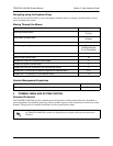
TRACER 4106/4206 System Manual Section 5 User Interface Guide
612804206L2-1A © 2004 ADTRAN, Inc. 47
>TRACER SYSTEM OPTIONS
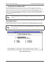
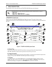
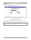
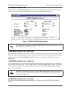
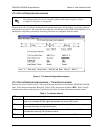
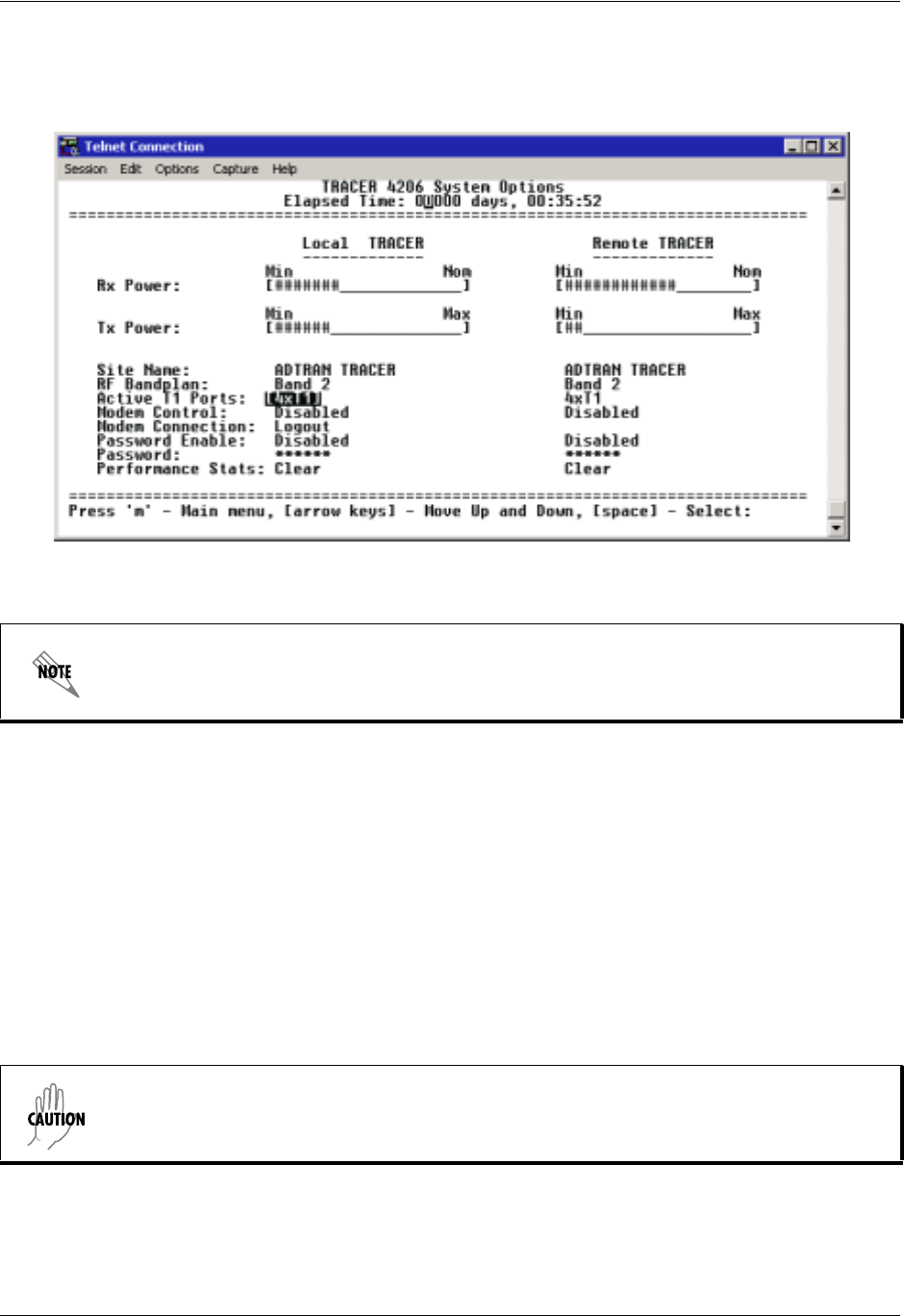
Figure 4 shows the TRACER 4106/4206 System Options menu page. System option parameters for both
the local and remote TRACER 4106/4206 units are available through this menu page.
Figure 4. TRACER 4106/4206 System Options
>TRACER SYSTEM OPTIONS > RX POWER
Displays the approximate receiver levels (for both the local and remote units) using a series of symbols (#).
The more symbols (
#) displayed, the stronger the signal. If the link is down in either direction, and remote
end data is unavailable,
DATA NOT AVAILABLE displays in place of the symbols (#). This parameter is
display only.
>TRACER SYSTEM OPTIONS > TX POWER
Allows the transmitter levels (for both the local and remote units) to be adjusted. The current transmitter
level is displayed using a series of symbols (
#). The more symbols (#) displayed, the stronger the signal. If
the link is down in either direction, and remote end data is unavailable,
DATA NOT AVAILABLE displays in
place of the symbols (
#).
>TRACER SYSTEM OPTIONS > SITE NAME
Provides a user-defined alphanumeric description (up to 25 characters) for the TRACER 4106/4206
system.
Press <O> from any menu in the TRACER 4106/4206 VT100 menu structure to access the
TRACER System Options menu page.
Reducing the transmitter power of the remote TRACER 4106/4206 could cause the RF link
to drop, requiring a technician to manually increase transmit power through the menu
system at the remote site.