


Section 5 User Interface Guide TRACER 4106/4206 System Manual
52 © 2004 ADTRAN, Inc. 612804206L2-1A
>T1X STATUS/CONFIGURATION/LOOPBACK > T1X LINE BUILD OUT
Configures the T1 for the appropriate line buildout, based on the distance to the T1 equipment. By default,
the line buildout for the TRACER 4106/4206 is
0 dB/133 FT.
>T1X STATUS/CONFIGURATION/LOOPBACK > ALARM REPORTING
Determines whether the TRACER 4106/4206 unit will report active alarms. If set to DISABLED, no alarms will
be displayed on this menu page. The
ALARM REPORTING parameter is independently configured for the local
and remote TRACER 4106/4206 units. When set to
DISABLED, the front panel LED alarms are also disabled
(OFF). By default, alarm reporting is set to
ENABLED.
>T1X STATUS/CONFIGURATION/LOOPBACK > SIGNALING
Configures the framing format for the T1 link for both the local and remote TRACER 4106/4206 units. The
TRACER 4106/4206 transports T1 data across the link (as long as the T1 signal is properly timed). Configure
the framing format (using the
SIGNALING menu) to enable the TRACER 4106/4206 to monitor incoming
framing error events and indicate problems with the attached metallic service. The TRACER 4106/4206
supports both extended superframe (
ESF) and superframe (D4) framing formats. By default, the signaling
method is set to
ESF.
>T1X STATUS/CONFIGURATION/LOOPBACK > LINE CODE
Sets the line coding for the T1 link. The TRACER 4106/4206 supports bipolar eight-zero substitution (B8ZS)
and alternate mark inversion (AMI) line coding. By default, the line code is set to B8ZS.
>T1X STATUS/CONFIGURATION/LOOPBACK > LOOP/NORMAL STATE
Controls the loop status of the T1 link. Activates/deactivates loopback conditions for testing purposes.
>T1X STATUS/CONFIGURATION/LOOPBACK > LOOP/NORMAL STATE > NORMAL
Defines the T1 link as normal data transport mode - there are no active loopbacks.
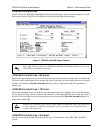
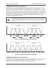
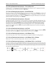
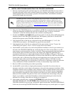
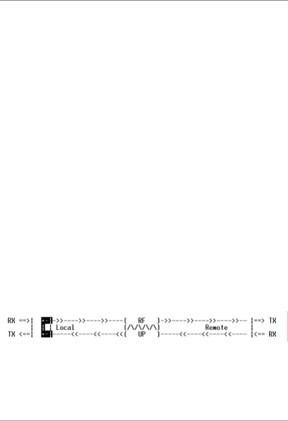
>T1X STATUS/CONFIGURATION/LOOPBACK > LOOP/NORMAL STATE > LINK [LOCAL]
Activates a loopback at the local TRACER 4106/4206 T1 framer towards the remote end of the wireless link
(see Figure 9). Use the local
LINK loopback to loop the data transmitted from the remote end of the link back
across the radio link to the remote end of the link. This loopback tests the integrity of the radio link and all the
associated digital and RF hardware.
Figure 9. T1 Local Link Loopback