Page 1
Section 61150.052L1-5, Issue 1
Part No.
1150052L1
61150.052L1-5A
Section 61150052L1-5
Issue 1, July 1995
CLEI Code # D4PBCU0_ _ _
MODEL ACT PSU
ADVANCED COMMUNICATIONS TERMINAL
POWER SUPPLY UNIT
INSTALLATION/MAINTENANCE
PRACTICES
CONTENTS
1. GENERAL .....................................................................1
2. INSTALLATION ............................................................1
3. CONNECTIONS ............................................................2
4. FACEPLATE INDICATORS .........................................2
5. MAINTENANCE ............................................................2
6. WARRANTY AND CUSTOMER SERVICE ..................2
FIGURES
Figure 1. ADTRAN ACT PSU ...........................................1
Figure 2. Connector Pin Assignments...........................2
TABLES
Table A. Basic Features .................................................1
Table B. ACT PSU Specifications..................................2
Table C. Faceplate Indicators ........................................2
C A U T I O N !
SUBJECT TO ELECTROSTATIC DAMAGE
OR DECREASE IN RELIABILITY.
HANDLING PRECAUTIONS REQUIRED.
Unit
ACT PSU
Features
Fuses incoming -48 V and 20 Hz
ringing voltage.
Converts -48 VDC to regulated +5
VDC, +12 VDC, and -12 VDC.
Outputs individually diode
isolated to allow redundant
operation.
Front panel test points for all
voltages.
Front panel indicators showing
the status of the unit.
Filters -48 V to provide -48 F for
the rest of the system.
Table A. Basic Features
1. GENERAL
1.1 This practice provides installation and mainte-
nance information for the ADTRAN Advanced
Communications Terminal Power Supply Unit (ACT PSU).
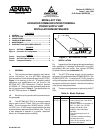
Figure 1 is a drawing of the unit. A detailed product
description and specifications can be found in the
ADTRAN ACT PSU Description Practice, Section
61150052L1-2. The part number and basic features for
the unit are provided in Table A. The specifications for
the ACT PSU are shown in Table B.
1.2 Revisions to this practice will be summarized in
this paragraph.
1.3 The ADTRAN ACT PSU is a common module
plug-in used in the ACT 2300, 1900, and 1950 channel
banks. The unit converts the -48 VDC input to +5 VDC,
+12 VDC, and -12 VDC output voltage levels to be used
by other common equipment and channel units. The unit
is also designed to operate in a parallel, redundant
fashion for increased system reliability.
Figure 1. ADTRAN ACT PSU
2. INSTALLATION
2.1 Inspect the unit for shipping damage immediately
after unpacking it. If damage is discovered, file a claim
immediately with the carrier; then contact ADTRAN
Customer Service (see subsection 6.2).
2.2 The ACT PSU plugs directly into the common
card area in the positions marked POWER SUPPLY A or
POWER SUPPLY B. To install the ACT PSU, grasp the
unit by the faceplate and push it firmly into the backplane
connector until the unit is seated. Lock the unit in position
using the two faceplate screws.
2.3 There are no adjustments or options for the ACT
PSU.