


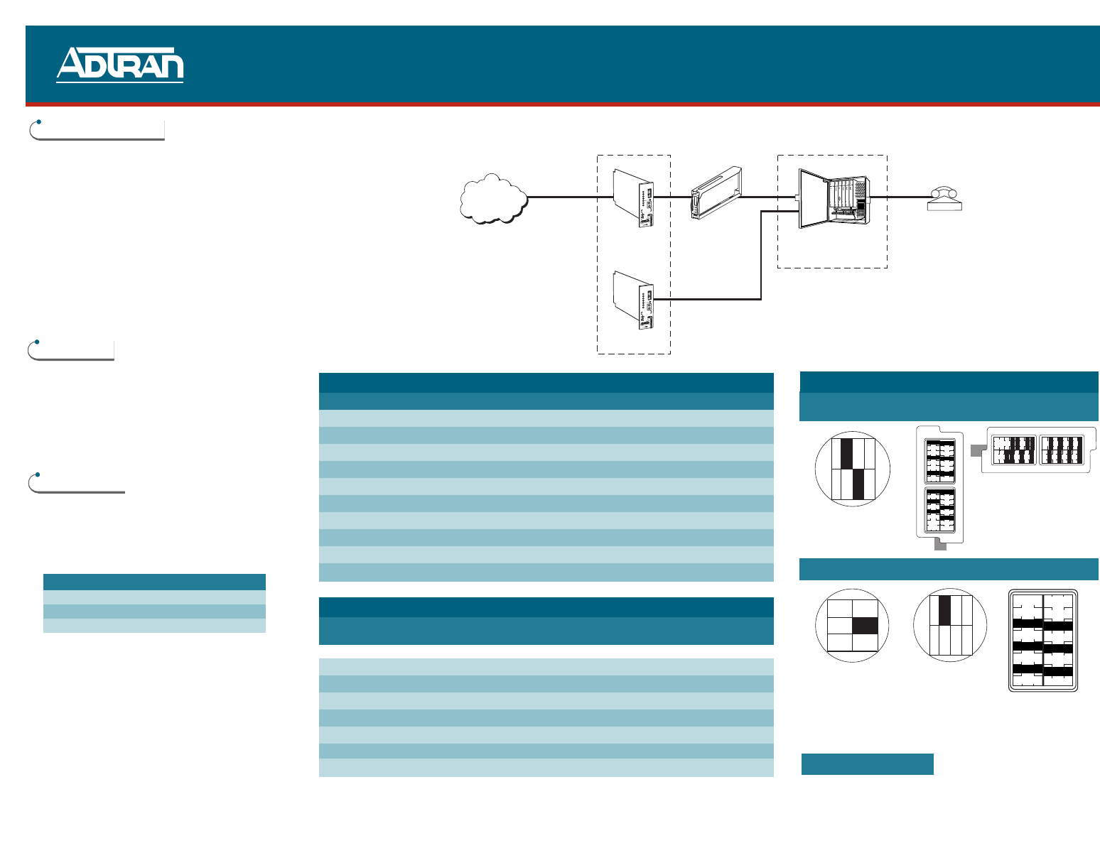
HOUSING DIAGRAMS
ADTRAN 8-slot AT&T/Keptel/ABACON
Above Ground Above Ground Below Ground
SPC 6-slot SPC 8-slot AT&T/Keptel
Above Ground Above Ground Above Ground
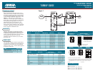
POWERING OPTIONS
The ICOT will power the entire Total Access
1000 System. When an HRE is used to extend
the range of the POTS circuits, a second ICOT
is used to provide auxiliary span power to the
system through additional copper pairs. (See
Figure 1). The Total Access 1000 system
continues to receive span power through the
HDSL loops. The second ICOT is only needed
for its span powering capacity. No circuit
information can be accessed from it. No
DSX-1 connections are necessary. The loop
will not train, and it will always show an alarm
condition. Applications using only U-BR1Tes
do not require an additional ICOT.
WARRANTY
ADTRAN will replace or repair this product
within the warranty period if it does not meet
its published specifications or fails while in
service. Warranty information can be found at
www.adtran.com/warranty. USA and
Canadian customer Faxback: (877) 457-5007,
Document 414.
COMPLIANCE
The 239 HRE complies with the requirements
covered under UL 60950 and is intended to be
installed in an enclosure with an Installation
Code (IC) of “B” or “E.” Ensure chassis ground
is properly connected.
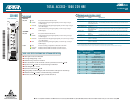
TURNUP GUIDE
PRICING AND AVAILABILITY 800.827.0807
TECHNICAL SUPPORT 800.726.8663
RETURN FOR REPAIR 256.963.8722
www.adtran.com
61179513L1-22A
ADTRAN 239 REPEATER HOUSINGS
PART # Description HRE Capacity CLEI Code* Material
1150027L1 4-slot Air Stub 4 DDMOABA1MA Stainless Steel
1150027L2 4-slot Gel Stub 4 DDMOBBA1MA Stainless Steel
1152010L3 2-slot Gel Stub 2 DDMOBAE1RA Valox Plastic
1152010L4 2-slot Air Stub 2 DDMOAAE1RA Valox Plastic
1150057L1 4-slot Air Stub 4 DDMODA01RA Stainless Steel
1150057L2 4-slot Gel Stub 4 DDMOCA01RA Stainless Steel
1150058L1 8-slot Air Stub 6 DDMOEE01RA Stainless Steel
1150058L2 8-slot Gel Stub 6 DDMOFE01RA Stainless Steel
1190816L1 16-slot Air Stub 16 DDMOES01RA Stainless Steel
1190816L2 16-slot Gel Stub 16 DDMOFS01RA Stainless Steel
HRE 239 DEPLOYMENT IN OTHER HOUSINGS
Company Description HRE Capacity Material
Above Ground Below Ground
AT&T, Keptel, ABACON 25-slot 12 16** Polymer
SPC 6-slot Air Stub 5 6 Stainless Steel
SPC 6-slot Gel Stub 5 6 Stainless Steel
SPC
†
8-slot Air Stub 7 8 Stainless Steel
SPC
≠
8-slot Gel Stub 7 8 Stainless Steel
Keptel 8-slot Air Stub 8 8 Valox Plastic
AT&T, Keptel 12-slot Air Stub 6 N/A Polymer
Lucent 100-slot 42 N/A Steel
12
4
578
1, 4, 7, 8, 11, 14, 15,
17, 19, 20, 23, 25
1, 3, 5, 7, 8,10, 12, 14, 15,
16, 18, 19, 20, 22, 24, 25
14
6
2
3
1234
57
8
1
3
5
7
9
11
Lucent 100 Slot
Above Ground
Filled:
Shelf 1: 1, 3, 5, 7, 9, 11
Shelf 2: 1, 3, 5, 7, 9, 11, 14, 16, 18, 20, 22, 24
Shelf 3: 1, 3, 5, 7, 9, 11, 14, 16, 18, 20, 22, 24
Shelf 4: 1, 3, 5, 7, 9, 11, 14, 16, 18, 20, 22, 24
* TIRKS function code for all cases is HTURENN
** 16 units can be loaded inside the 819 housing for all below ground mounting orientations.
if the 819 housing is mounted specifically in the vertical, stub down direction, 18 units
can be loaded in slots 1, 3, 5, 7, 8, 10, 12, 13, 14, 15, 17, 18, 19, 20, 21, 22, 24, 25.
† Vented ≠ Pressurized
1, 3, 5, 7, 9, 11
P
S
U
1
1
7
9
0
0
8
L
1
P
O
W
E
R
A
T
M
B
C
U
1
1
7
9
1
1
2
L
1
N
E
T
W
O
R
K
T
E
S
T
A
D
M
I
N
A
D
S
L
1
1
7
9
4
1
3
L
1
L
O
O
P
1
2
3
4
A
D
S
L
1
1
7
9
4
1
3
L
1
L
O
O
P
1
2
3
4
A
D
S
L
1
1
7
9
4
1
3
L
1
L
O
O
P
1
2
3
4
1
1
7
9
1
0
9
L
1
H
L
I
U
L
O
O
P
1
2
3
4
Switch
N
O
S
X
S
Y
N
C
C
R
C
Q
M
D
I
S
C
R
E
M
N
O
D
S
U
L
B
K
R
X
(
O
U
T
)
T
X
(
I
N
)
T
R
D
D
B
1
2
9
1
0
0
4
D
D
S
T
o
t
a
l
R
e
a
c
h
O
N
1
9
.
2
5
6
6
4
S
C
9
.
6
4
.
8
2
.
4
Q
M
L
L
B
678954321
A
P
N
O
S
X
S
Y
N
C
C
R
C
Q
M
D
I
S
C
R
E
M
N
O
D
S
U
L
B
K
R
X
(
O
U
T
)
T
X
(
I
N
)
T
R
D
D
B
1
2
9
1
0
0
4
D
D
S
T
o
t
a
l
R
e
a
c
h
O
N
1
9
.
2
5
6
6
4
S
C
9
.
6
4
.
8
2
.
4
Q
M
L
L
B
678954321
A
P
ICOT
Modules
Total Access 1000 RT
System
HRE
Auxiliary
Power
Pairs
Phone
T1
TR-08
SF
or
ESF
Central Office
Customer Premises
Code Input Output
Power Code (PC) C C
Telecommunication Code (TC) X X
Installation Code (IC) A –
Figure 1