


TOTAL ACCESS 1200 IP NETWORK MODULE
JOBAID
61179611L3-22A
0307
TOTAL ACCESS 1200
IP NETWORK
MODULE
CLEI: VAA1GG0E_ _
■ For a complete Installation and Maintenance Practice (P/N 61179611L3-6): 877-457-5007, Document 973. Please have your fax number ready. ■
C A U T I O N C A U T I O N !
SUBJECT TO ELECTROSTATIC DAMAGE
OR DECREASE IN RELIABILITY.
HANDLING PRECAUTIONS REQUIRED.
#61179611L3-22A#
DESCRIPTION
The IP Network Module provides an Ethernet uplink for the Total Access
®
1200 chassis. It
can provide up to 24 ports of ADSL plus POTS toward customers. Its learning bridge
configuration can support up to 4096 bridge table entries. The IP Network Module acts
as a bridge and will "learn" the Ethernet MAC addresses connected to the user ports.
The following features are supported on the IP Network Module:
■ A single Ethernet 10/100 feed for both data and in-band management
■ One Virtual Circuit per port
■ Learning Bridge configuration
■ An alarm log of system level events
■ An RJ-45 type connector for the Ethernet connection
■ Operates over an extended temperature range –40°C to +70°C
■ Front Panel indication of Ethernet status
■ Front access to all connections
■ Provisioning and alarm monitoring via menus or remote access via Telnet
■ NEBS Level 3, GR-1089-CORE and UL 60950 compliant
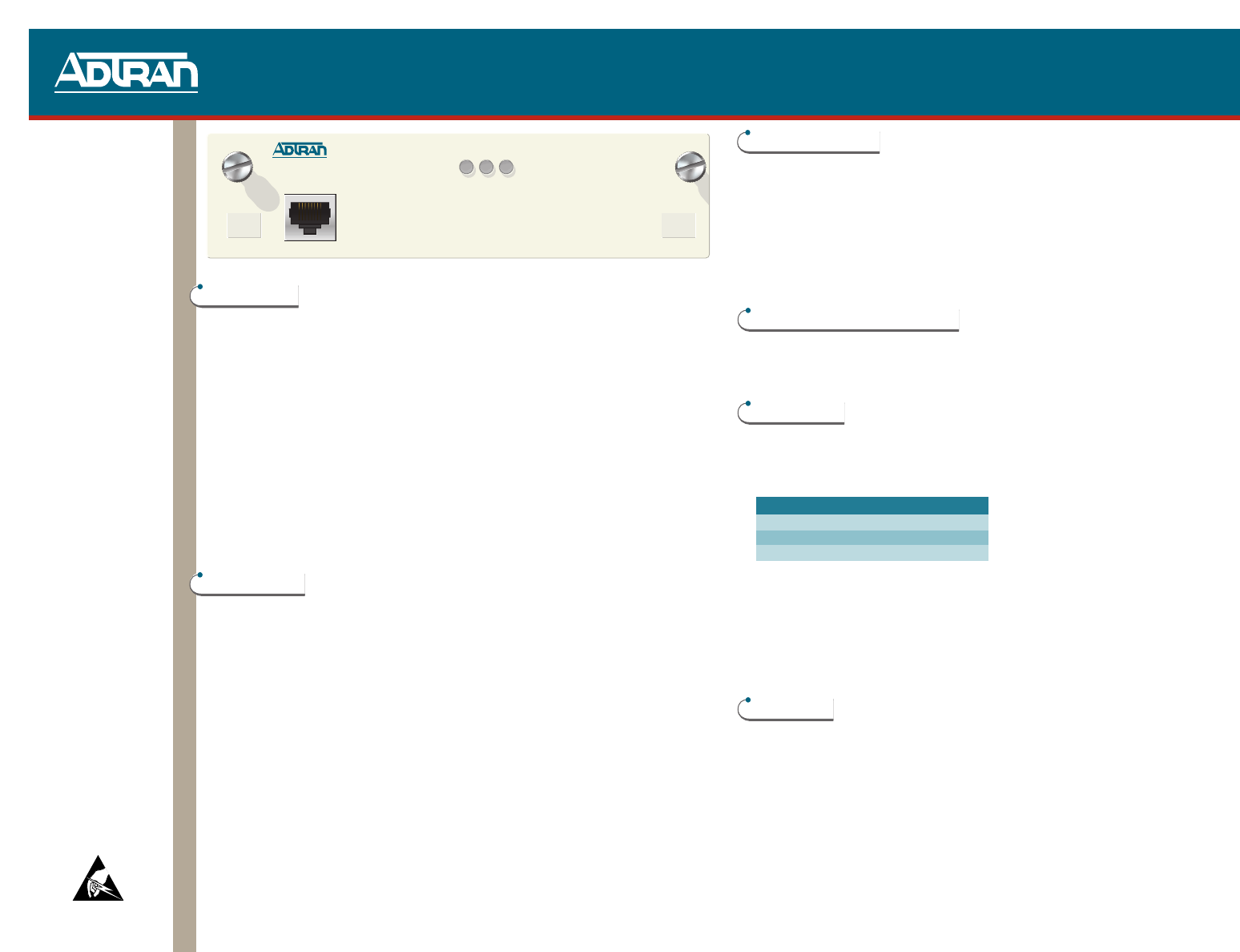
CONNECTIONS
The IP Network Module plugs directly into the Total Access 1200 (19- or 23-inch) rack
mounted shelf. The Ethernet feed is connected to the front of the module through the
RJ-45 plug.
TURN-UP STEPS
To install the IP Network Module, perform the following steps:
After unpacking the IP Network Module,inspect it for damage. If damage is found,file a
claim with the carrier and then contact ADTRAN Customer Service.
ADTRAN recommends that all power be removed from the Total Access 1200 before
removing or replacing the IP Network Module.
Loosen screws on the previous module and remove it, if so equipped.
Insert new module in the slots on the left and right and slide it securely into place.
Tighten the two screws to secure the module in the chassis.
Insert the Ethernet cable with the RJ-45 plug in the jack on the front of the module.
Restore power to the Total Access 1200.
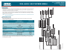
FRONT PANEL LEDS
The front panel contains three LEDs that monitor status.
ETH ● Green Connected 100BaseT
● Yellow Connected, 10BaseT
● Red Not connected
TD ●● Off No Traffic
✷ Flashing Green Transmit Traffic
RD ●● Off No Traffic
✷ Flashing Green Transmit Traffic
OPERATIONAL SPECIFICATIONS
■
Operates from A or B –42 VDC to –56 VDC input voltage power feeds.
■
Operates over extended temperature range of (–40°C to +70°C)
■
Storage –40°C to +85°C. Relative humidity to 95 percent, noncondensing.
COMPLIANCE
This product is NRTL listed to the applicable UL standards. The IP Network
Module is intended for installation in a type “B” or “E” enclosure in a Restricted
Access Only area. The Total Access 1200 shelf Frame Ground terminal must be
connected to an earth ground.
This device complies with Part 15 of the FCC rules. Operation is subject to the
following two conditions: (1) This device may not cause harmful interference, and
(2) this device must accept any interference received, including interference that
may cause undesired operation.
Changes or modifications not expressly approved by ADTRAN could void the user’s
authority to operate this equipment.
WARRANTY
ADTRAN will replace or repair this product within the warranty period if it does not
meet its published specifications or fails while in service. Warranty information
can be found at www.adtran.com/warranty. U.S. and Canada customer Faxback:
877-457-5007, Document 414.
1
2
3
4
5
1179611L3
IP MODULE
ETHERNET
ETH TD RD
Code Input Output
Power Code (PC) C C
Telecommunication Code (TC) X –
Installation Code (IC) A –
6
7