For more detailed documentation, visit us online at www.adtran.com
Total Access 850 DSX-1 Module P/N 1200385L1
Quick Start Guide
Quick Start Guide, 61200385L1-13A, September 2004 Technical Support 1-888-4ADTRAN (1-888-423-8726) © 2004 ADTRAN, All Rights Reserved
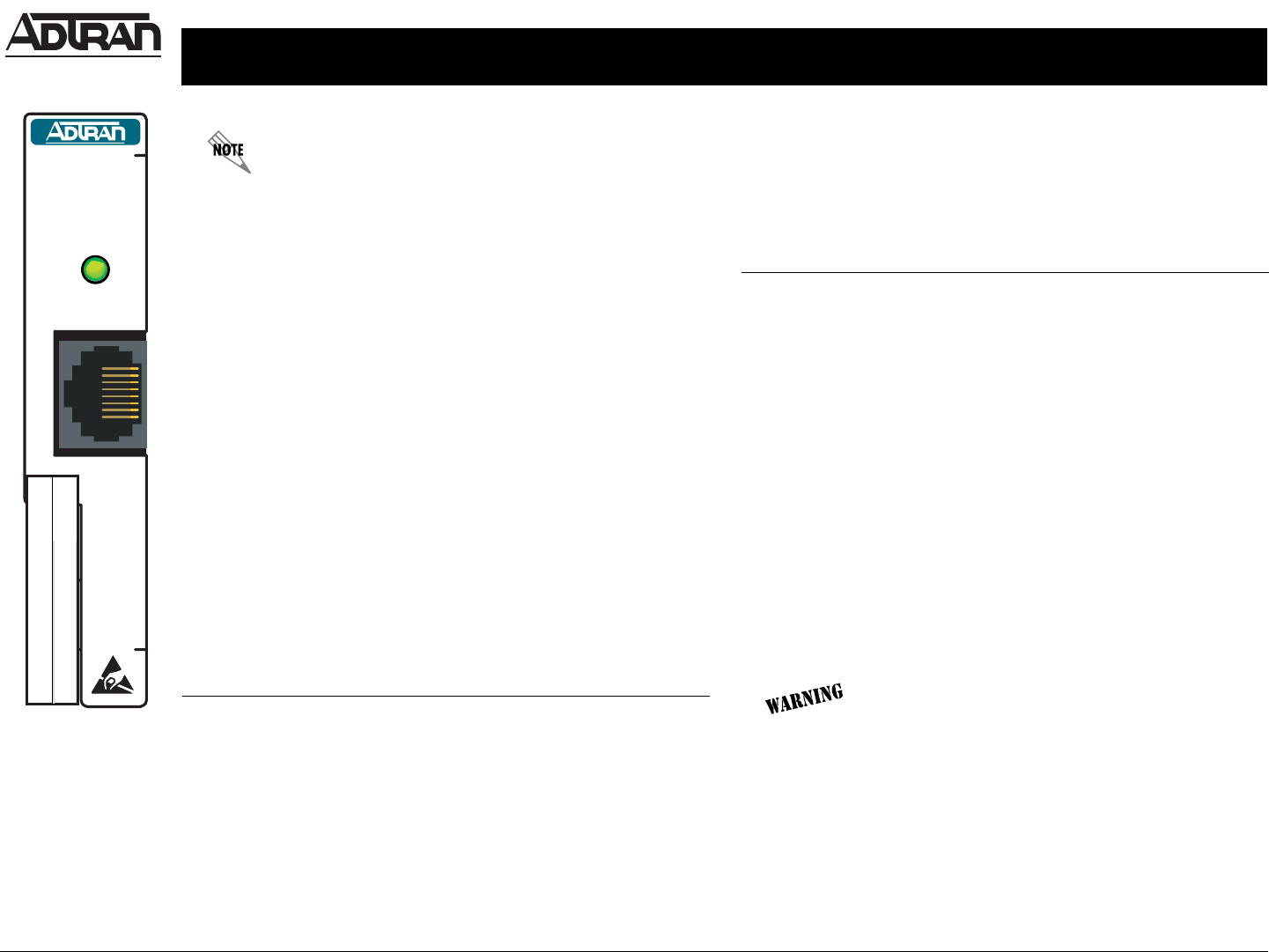
DSX-1
1200385L1
STATUS
The Total Access 850 DSX-1 Module is for use with the Router Controller Unit (RCU) only. This module provides data support (no
RBS for voice applications) for Customer Premises Equipment (CPE) and CANNOT be connected to network resources; this
module is for connection to CPE only.
SPECIFICATIONS
Capacity T1: 1 to 24 DS0s
Framing ESF and SF (D4)
Line Build Out DSX-1: 0 to 655 feet in 133-ft increments
Line Coding AMI (alternate mark inversion) or B8ZS (bipolar 8
zero substitution)
Line Rate 1.544 Mbps ± 75 bps
Terminating
Impedance
100 Ω ± 5%
Tests Self-test, local line, local payload, remote line,
and remote payload
Environmental Operating Temperature: 0° C to 50° C
Storage Temperature: -40° C to +70° C
Relative Humidity: Up to 95% noncondensing
LED DESCRIPTIONS
Color Description
OFF No power to the system
GREEN DSX-1 signal is present and synchronized; the
DSX-1 channels are configured for use
RED Active channel alarm on the DSX-1 interface
Solid AMBER Channel test in progress
Blinking AMBER Module is initializing (during startup)
DSX-1 CONNECTION PINOUT
Pin Name Description
1 R1 | RXDATA-RING Receive data from the network
(RING)
2 T1 | RXDATA-TIP Receive data from the network (TIP)
3 UNUSED –––
4 R | TXDATA-RING Transmit data towards the network
(RING)
5 T | TXDATA-TIP Transmit data towards the network
(TIP)
6-8 UNUSED –––
INSTALLATION INSTRUCTIONS
1. Remove the cover plate from the appropriate slot of the
Total Access 850 chassis.
Dangerous voltage is exposed when the
cover plate is removed.
2. Position the module to fit in the lower and upper grooves.
3. Slide the module into the option slot, pressing equally on the
top and bottom of the faceplate until the module is firmly
positioned against the back of the chassis.
4. Push in the ejector on the lower left-hand side of the module
to finish seating the module.


