


104 Installation and User’s Guide
4 Servicing the System
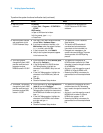
To troubleshoot the system
Most system problems are caused by faulty cabling or switch
configurations.
Refer to Figure 20 on page 53 and Figure 19 on page 51 and do the
following:
✔ Check system connections and settings:
1 system connections to the DUT
2 system interconnections
3 GPIB cabling
4 GPIB address settings
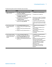
If the cabling and switch configurations are verified correct, do the
following:
✔ Complete the Agilent E8364B PNA Series vector network analyzer
operator’s check in “Performing the RF Subsystem Functional
Verification Test" on page 125.
✔ Complete the Agilent 4156C precision semiconductor parameter
analyzer self- test in “Performing the DC Subsystem Functional
Verification Test" on page 121.
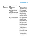
✔ Complete the Agilent 4284A self- test by cycling the instrument’s line
power. If errors occur, refer to Appendix B in the precision LCR meter
operation manual. The operation manual is included in with the
Agilent 85225F performance modeling system.
✔ If you suspect trouble with the E2050B, see “Chapter 4
Troubleshooting” in the E5810A LAN/GPIB gateway installation and
configuration guide.
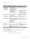
✔ Complete the Agilent E5250A self- test and leak test found in Chapter 3
of the low leakage switch mainframe user’s guide. The user’s guide is
included with the Agilent 85225F performance modeling system.
If a problem with one of the system components is found, refer to the
troubleshooting and repair information in the individual instrument’s
product documentation.
For more information, see “To receive additional assistance" on page 107.