


Introducing the Agilent 85225F Performance Modeling System 1
Installation and User’s Guide 21
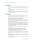
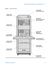
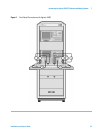
Agilent E5270B 8-Slot Precision Parametric Measurement Mainframe
The Agilent E5270B provides DC force (supply) and sense (measure)
capability from its plug- in source/monitor units.
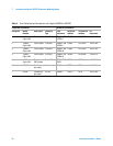
The Agilent E5280A plug- in high power source/monitor unit provides up
to 200 volts of potential and 1 amp of current to the device under test.
The Agilent E5281A plug- in medium power source/monitor unit provides
up to 100 volts of potential and 200 milliamps of current to the device
under test.
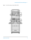
The Bias Networks
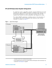
The Agilent 11612V Option K11 and K21 bias networks combine the DC
and RF signals and apply them simultaneously to the device under test
(DUT). The bias networks are configured with 2.4 mm DC/RF output
connectors for connection to a DUT, a test fixture, or probe station, as
shown in Figure 21 on page 54.
CAUTION
Exposing the bias networks to currents greater than 500 milliamps or voltages
greater than 40 volts will result in severe damage. Do not exceed these values
while using the bias networks. Remove the bias networks from the circuit if
greater voltages or currents are required.