


22 Installation and User’s Guide
1 Introducing the Agilent 85225F Performance Modeling System
Component Integration
System component integration is performed at the Agilent Technologies
factory. The individual components are placed into the rack, and the
required cabling is connected between the instruments.
After factory integration, the system is tested to verify functional
performance.
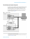
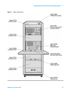
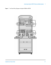
The Agilent 85225F performance modeling system includes the following
components, as shown in Figure 2 on page 23:
• Agilent E8364B PNA Series vector network analyzer
• Agilent 4156C precision semiconductor parameter analyzer (or
optionally Agilent E5260A or E5270B)
• Agilent 11612V Option K11 bias network (port 1)
• Agilent 11612V Option K21 bias network (port 2)
• Agilent 85133F flexible test port cable set
• Agilent E3661B 1.6 meter rack cabinet
• filler panels, feedthrough panels, work surface, cables, and adapters
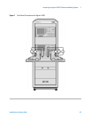
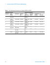
For systems with Agilent 4156C, front panel connections are listed in
Table 3 on page 24 and illustrated in Figure 3 on page 25.
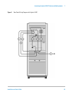
For systems with Agilent 4156C, rear panel connections are listed in
Table 5 on page 28 and illustrated in Figure 5 on page 29.
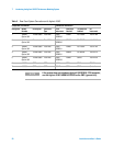
For systems with Agilent E5260A or E5270B, front panel connections are
listed in Table 4 on page 26 and illustrated in Figure 4 on page 27.
For systems with Agilent E5260A or E5270B, rear panel connections are
listed in Table 6 on page 30 and illustrated in Figure 6 on page 31.