


48 Installation and User’s Guide
1 Introducing the Agilent 85225F Performance Modeling System
Component Integration
System component integration is performed at the Agilent Technologies
factory. The individual components are placed into the rack, and the
required cabling is connected between the instruments.
After factory integration, the system is tested to verify functional
performance.
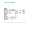
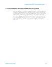
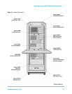
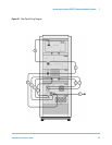
The Agilent 85225F performance modeling system includes the following
components, as shown in Figure 18 on page 49:
• Agilent E8364B PNA Series vector network analyzer
• Agilent 4156C precision semiconductor parameter analyzer with
optional Agilent 41501B SMU/PGU expander (or optionally Agilent
E5260A or E5270B)
• Agilent 11612V Option K11 bias network (port 1)
• Agilent 11612V Option K21 bias network (port 2)
• Agilent 4284A precision LCR meter
• Agilent 35670A dynamic signal analyzer
• Stanford Research SR 570 low noise current amplifier
*
• Agilent 85133F flexible test port cable set
• Agilent E3661B 1.6 meter rack cabinet
• filler panels, feedthrough panels, work surface, cables, and adapters
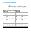
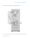
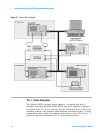
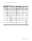
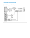
System front panel connections are listed in Table 10 on page 50 and
illustrated in Figure 19 on page 51.
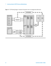
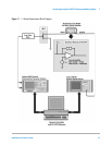
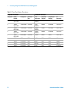
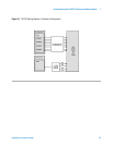
System rear panel connections are listed in Table 11 on page 52 and
illustrated in Figure 20 on page 53.
* Customer supplied, not included with system.