


76 Installation and User’s Guide
2 Installing the System
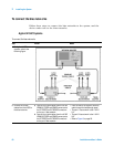
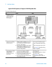
To ensure your safety while using the system
This product has been designed and tested in accordance with
international standards. Bias current and voltage are supplied to the DUT
from the DC subsystem. This instrument can force dangerous voltages to
the FORCE, SENSE, and GUARD connectors. DC subsystem is connected to
the device through the bias networks and test fixture or probe station.
WARNING
Failure to comply with the following precautionary safety instructions prior to
operating the system could result in serious injury or death.
With some installed options, the Agilent 4156C or Agilent E5260A/70B used in
this system can supply voltages up to ±200 volts DC. Depending on operating
conditions, hazardous voltages can be present at points in the system that
could potentially come in contact with the system operator.
Before operating the system, follow these steps to ensure your safety.
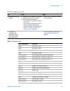
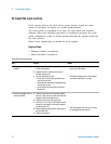
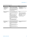
To ensure your safety while using the system
Step Action Notes
1 Never operate the system
without a safety earth
ground.
a Ensure that a safety earth ground is
connected between the system power
distribution unit and the line power source.
b If it is likely that the safety earth ground
has been impaired, the system must be
rendered inoperative and secured against
unintended operation.
• Capacitors within the system
components can remain charged even
after the system is disconnected from
its line power source.
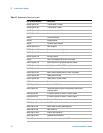
2 Never attempt to service
the system.
a Contact Agilent Technologies if service is
required.
• The system may only be serviced,
adjusted, maintained, or repaired by
qualified personnel.
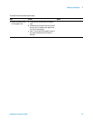
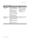
3 Open the DC subsystem
interlock connection
whenever possible.
a Close the DC subsystem INTLK (Interlock)
connection only when voltages greater
than ±42 volts DC are required.
• Depending on installed options, the
SMU output can be as high as
±200 volts DC. As long as the INTLK
connection is open, the voltage is
clamped to ±42 volts DC maximum.
• For instruction on installing an
interlock switch on a shielding box, see
“To Make an Interlock Connection” in
the 4156C user’s guide (volume 1) or
“Connecting the Interlock Terminal” in
chapter 3 of the E5270 user’s guide.