


78 Installation and User’s Guide
2 Installing the System
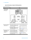
Precautions for Performing Floating-Ground Measurements
IC- CAP measurements can be performed with the device in a
floating- ground configuration. This prevents ground- loop noise and, in the
case of a bipolar junction transistor, damage to the device under test.
A floating- ground configuration is created by removing the shorting bar
that connects the CIRCUIT COMMON and CHASSIS GROUND terminals.
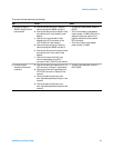
If you are making measurements in a floating- ground configuration, ensure
that the shorting bar is disconnected between the CIRCUIT COMMON and
CHASSIS GROUND terminals.
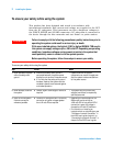
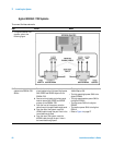
To perform floating-ground measurements
When floating ground measurements are necessary, remove the rear front
panel shorting bar connecting the CIRCUIT COMMON and CHASSIS
GROUND terminals.
When the shorting bar is removed, you must drive the DUT circuit
common with either an SMU, GNDU, or by connecting directly to the DC
subsystem circuit common. The circuit common can be found at the DUT
ends of the SMU and GNDU cables.
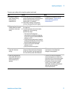
Read “Precautions for Performing Floating- Ground Measurements" on
page 78, then follow these steps to connect the CIRCUIT COMMON to an
external ground.
WARNING
A potential shock hazard exists when the shorting bar is disconnected for
floating-ground measurements. Do not touch any of the DC subsystem rear
panel connectors while a floating ground measurement is in progress.
NOTE
The circuit common is not connected through the bias networks.
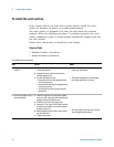
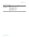
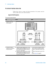
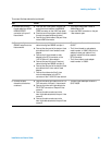
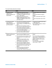
To connect an external ground to the circuit common
Step
1 Remove the shorting bar connecting the CIRCUIT COMMON and CHASSIS
GROUND terminals.
2 Connect the external ground to the CIRCUIT COMMON of the DC subsystem.