


Installing the System 2
Installation and User’s Guide 83
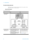
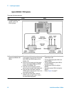
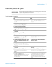
4 Connect the Agilent
E8364B test ports to the
bias networks.
a Connect one end of the port 1 test port
cable to the Agilent E8364B test port 1.
b Connect the other end of the test port 1 test
port cable to the 2.4 mm female-to-male
adapter.
c Connect the 2.4 mm female-to-male
adapter to the RF IN connector on the
11612V Option K11 bias network.
d Connect one end of the port 2 test port
cable to the Agilent E8364B test port 2.
e Connect the other end of the test port 2 test
port cable to the 2.4 mm male-to-male
adapter.
f Connect the other end of the 2.4 mm
male-to-male adapter to the RF IN
connector of the 11612V K21 bias network.
• The test port cables model number is
85133F.
• The 2.4 mm female-to-male adapter
model number is 11900C. Without this
adapter, the test port cable will not
properly mate with the bias network
RF IN connector.
• The 2.4 mm male-to-male adapter
model number is 11900A.
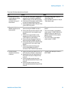
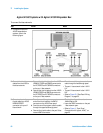
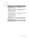
5 Connect the bias
networks to the device
under test.
a Connect one semi-rigid cable to the RF/DC
OUT connector of the port 1 bias network.
b Connect the other semi-rigid cable to the
RF/DC OUT connector of the port 2 bias
network.
c Connect the device under test to the
semi-rigid cable attached to the port 1 bias
network.
d Connect the device under test to the
semi-rigid cable attached to the port 2 bias
network.
• The semi-rigid cables part number is
85107-20004.
To connect the bias networks (continued)
Step Action Notes