


Verifying System Functionality 3
Installation and User’s Guide 95
Performing the System Functional Verification Test
Complete the following steps to verify system functionality using the
supplied Agilent 8490D 10 dB fixed RF attenuator as the device under
test.
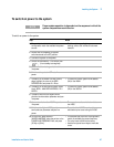
To perform the system functional verification test
Step Action Notes
1 Switch on power to the
system.
a Complete the steps listed in “To switch on
power to the system" on page 87.
• Proper system function is dependent
upon the order in which the system
components are switched on.
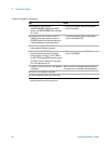
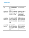
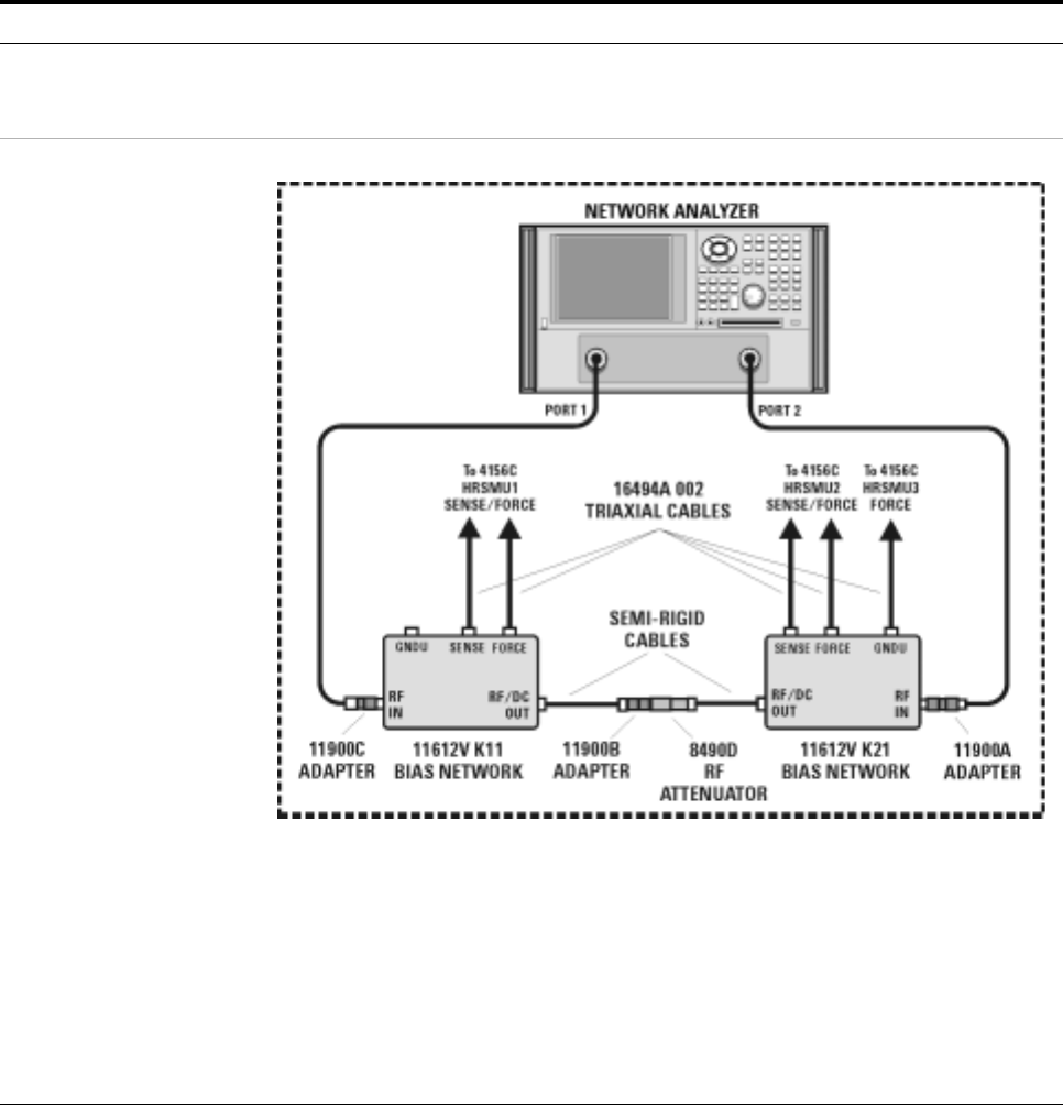
2 Connect the device under
test to the bias networks.
a Refer to the following figure.
b Connect one end of the 2.4 mm
female-to-female adapter to the semi-rigid
cable attached to the RF/DC OUT
connector of the port 1 bias network.
c Connect male end of the attenuator to the
other end of the 2.4 mm female-to-female
adapter.
d Connect the female end of the attenuator to
the semi-rigid cable attached to the RF/DC
OUT connector of the port 2 bias network.
• The 2.4 mm female-to-female adapter
is a 11900B. Use the 11900B provided
in the calibration kit.
• The port 1 bias network is a 11612V
K11.
• The port 2 bias network is a 11612V
K21.