


85330A Multiple Channel Controller 9-5
Service
Theory of Operation
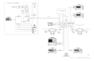
The 85330-60002 card contains the TTL trigger and ready lines that
interface to the 8530A microwave receiver, the RF source, and the LO
source. The communication to the switch control unit is through sets of
parallel twisted-pair wires and bias wires. These wires enable placement of
the switches next to the transmit and receive devices. This minimizes the RF
path lengths to the external mixer modules and therefore decreases the
amount of RF losses.
Configuration of the 85330A is achieved by sending a series of GPIB
commands to the mainframe prior to the runtime. To initiate the runtime
sequence, a GPIB command is issued to the controller, or, the controller
begins the measurement sequence, or waits for a trigger signal to the
EVENT TRIG to begin the sequence. For the latter, the controller repeats the
sequence for each trigger sent to the EVENT TRIG.
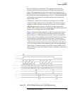
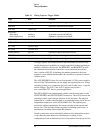
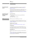
Figure 9-2 shows the timing sequence of a typical measurement using the
85330A. Table 9-1 on page 9-6 shows the time required for each trigger
shown in Figure 9-2. This measurement not only controls a transmit and
receive switch, but may optionally control the RF and LO sources for high
speed frequency switching during the measurement. Upon receiving a
trigger from the Positioner Controller or other trigger source, the 85330A
issues the receiver trigger, waits for the receiver ready line, asserts the next
set of switch states, waits for the switches to settle, and issues the receiver
another trigger. To change frequency, the 85330A triggers the RF and LO
sources and waits for the source ready lines before proceeding to the next set
of switch states.
Figure 9-2 85330A Timing Sequence of a Typical Measurement