


9-6 85330A Multiple Channel Controller
Service
Theory of Operation
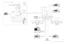
For large systems, the distance between the transmitters and receiver may
exceed the physical capabilities of a single controller. For these applications,
multiple controllers can be used. The REMOTE1 and REMOTE2 provide
the communications between controllers via two balanced twisted-pair
wires, similar to RS-422. In defining the runtime parameters, the event
sequence is also defined which enables the controllers to operate in unison
via these wires.
The AUX POWER IN allows for use of an external ±12 Vdc power supply to
be used if the VXI mainframe can not supply the required power for a large
switching system, or to compensate for local control cable losses, or special
switch voltages. The AUX 1 and AUX 2 outputs can provide a
user-controllable TTL line for special applications.
The 85330-60002 card communicates with the switch control units via the
SWITCH PORT1 and SWITCH PORT2 connectors. These SCUs decode the
switching control signals and provide bias for the Switches. The physical
connection of a switch control module is accomplished using one of the two
independent output ports on the 85330-60002 card. The separate ports
provide the cabling requirements for remote switches to the transmit and
receive sites. The cascading feature provides for building switch trees, or
simultaneous switching into multiple RF channels.
Switch control units can be individually addressed for independent control,
or can share the same address for simultaneous switching or tree
configurations. Each module has two bits of unit-address decode and six bits
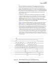
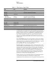
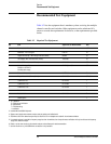
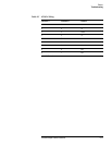
Table 9-1 Timing Sequence Trigger Widths
Trigger Width Description
EVENT TRIGGER 1 µs≤t
ev
≤1 ms Trigger width dependent on trigger source
MEAS BUSY Dependent on measurement time of 85330A
RCVR TRIG 1µs≤t
rc
≤3 µs
RCVR READY:
Switch Settling
Receiver Measurement
Default 2 µs
typ. ≥200 µs
Set by 85330 command- RUNT:SWIT:DEL
Dependent on measurement time of 8530A
SWITCH PORT 1 Variable Dependent on RCVR TRIG and RCVR READY lines
SWITCH PORT 2 Variable Dependent on RCVR TRIG and RCVR READY lines
SRC 1 TRIG 10 µs≤t
sr1
≤14 µs
SRC 2 TRIG 10 µs≤t
sr2
≤14 µs
Frequency switching typ ≥5 ms Dependent on frequency switching time of source
SRC 1 READY typ 1 µs Trigger width dependent on trigger source
SRC 2 READY typ 1 µs Trigger width dependent on trigger source