


9-10 85330A Multiple Channel Controller
Service
Troubleshooting
Troubleshooting
Troubleshooting the
System
An understanding of how the 85330A system operates is required before
undertaking the troubleshooting of this system. Please read “Theory of
Operation” on page 9-2.
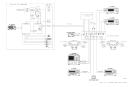
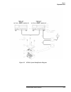
This system may be broken down into four parts: multiple channel controller
(mainframe), switch control unit, RF switch, and cables. In order to
determine which part of the system is not working correctly, a performance
verification may be run. For more information, see Chapter 2, “Performance
Verification.”
Troubleshooting the
Multiple Channel
Controller
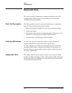
Turn ON Self Check
The following screen should appear when you turn the 85330A ON.
Select an instrument._
SYSTEM 85330A IBASIC
(see note below)
NOTE IBASIC is present only if the IBASIC option is installed.
If you see this display, go on to the next troubleshooting section. If you do
not see this display, load the 85330A downloadable driver files as explained
in Chapter 1, “Installation.”
Multiple Channel Controller
Run the test “Verifying the Multiple Channel Controller” on page 2-6.
VXI Mainframe
For troubleshooting information on the E1301B VXI mainframe, see the
Service chapter in the Agilent E1301B Service Manual. There are a couple
of VXI mainframe self tests that can be used, as well as the command
*TST?.
85330-60002 Card
The multiple channel controller tests, shown above, will check this plug-in
card.
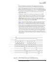
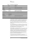
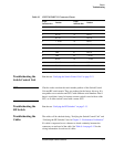
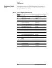
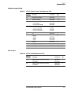
To check the SWITCH PORT1 and SWITCH PORT2 output connector, refer
to Table 9-3 on page 9-11 for each control line function. Use a digital scope
or a logic analyzer to monitor these lines.