


9-24 85330A Multiple Channel Controller
Service
Adjustments
Switching from the
Internal to External
Power Supply
This set of jumpers sets the 85330-60002 card to use in the internal VXI
power supply to bias the remote RF switches and Switch Control Units, or to
use the AUX POWER IN connector to bias the switches and SCUs. The
internal power supply is used when there is few SCUs and RF switches. The
AUX POWER IN is used when there are a large number of switches and
SCUs, or if the switches require a special dc voltage, or to compensate for
losses in a long Local Control Cable. The default is the internal power
supply.
To set these jumpers, perform the following on the 85330-60002 card. This
card must be removed before changing this switch. Refer to “Assembly and
Disassembly” on page 9-19 for information on removing the card.
1. Locate the jumpers W1 and W2 near the rear panel of the 85330-60002.
They will be next to the AUX POWER IN connector.
2. To set the card to the internal supply, the W1 jumper should go from
+12V to INT, and the W2 jumper should go from −12V to INT.
3. To set the card to the AUX POWER IN supply, the W1 jumper should go
from +12V to AUX, and the W2 jumper should go from −12V to AUX.
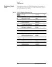
Required Mating Connector
A Molex Mini-Fit Jr model 5557 (Molex p/n 39-01-2105) receptacle is
required. At least three wire crimp terminals are required: 4.2 mm Pitch
Mini-Fit Family Terminal-crimp, Female model 5556 (Molex p/n
39-00-0059).
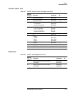
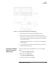
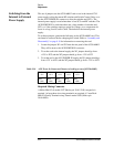
Table 9-10 AUX Power In Connector Pinouts (as looking at rear of 85330-60002)
Pin 10
−12 V
Pin 9
+12 V
Pin 8
+12 V
Pin 7
+12 V
Pin 6
+12 V
Pin 5
−GND
Pin 4
+GND
Pin 3
+GND
Pin 2
+GND
Pin 1
+GND