


85330A Multiple Channel Controller 2-7
Performance Verification
Verifying the Multiple Channel Controller
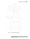
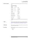
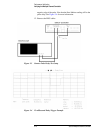
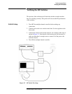
Figure 2-2 Switch Control Unit Output Connector Voltages
Inputs/Outputs Press the following on the multiple channel controller:
[Clear Instr] [Select Instr]
You should see the following display:
Select an instrument._
SYSTEM 85330A IBASIC
(see note below)
NOTE IBASIC is only present if the IBASIC option is installed.
This is the MAIN MENU.
Output Trigger Test The following test will determine if the rear-panel ports output the correct
signals. Note that a single press on the specific
{TRIGGER} key will cause a
single trigger pulse. If you hold down this key, a train of trigger pulses will
be outputted.
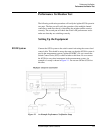
1. Connect a BNC cable between Channel 1 of the oscilloscope and the
multiple channel controller rear panel BNC connector that is being
tested.
2. On the oscilloscope, press:
[RECALL] [1]
3. Connect the BNC cable to the RCVR TRIG connector on the multiple
channel controller, and press:
{85330A} {TRIGGER} {RCVR}
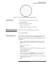
On the oscilloscope, press [CLEAR DISPLAY]. You should see a negative
pulse, with an approximate width of one to three microseconds.
4. Connect the BNC cable to the SRC 1 TRIG connector on the multiple
channel controller, and press:
{SRC_1}