


2-8 85330A Multiple Channel Controller
Performance Verification
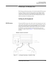
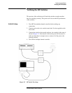
Verifying the Multiple Channel Controller
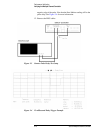
On the oscilloscope, press [CLEAR DISPLAY]. Set the [TIMEBASE] to {5 us/Div}.
You should see a positive pulse, with an approximate width of 10 to 14
microseconds.
5. Connect the BNC cable to the SRC 2 TRIG connector on the multiple
channel controller, and press:
{SRC_2}
On the oscilloscope, press [CLEAR DISPLAY]. You should see a positive
pulse, with an approximate width of 10 to 14 microseconds.
6. Remove the BNC cable from the multiple channel controller.
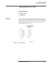
Pulse Receive and
Cycle Test
The following test will determine if the rear panel ports successfully sense
the trigger pulses. These tests will output a train of 100 pulses.
1. Press the following on the multiple channel controller:
[Clear Instr] [Select Instr] {85330A}
2. Connect a BNC cable between the RCVR READY and RCVR TRIG
connectors. Press:
[More] {TEST} {RCVR} [1] [0] [0] [Return]
If the test is successful, the RCVR menu will appear on the display. If
the test fails, the following error message will appear:
-214, Trigger deadlock
3. Connect a BNC cable between the SRC1 READY and SRC1 TRIG
connectors. Press:
{SRC_1} [1] [0] [0] [Return]
If the test is successful, the RCVR menu will appear on the display. If
the test fails, the following error message will appear:
-214, Trigger deadlock
4. Connect a BNC cable between the SRC2 READY and SRC2 TRIG
connectors. Press:
{SRC_2} [1] [0] [0] [Return]
If the test is successful, the RCVR menu will appear on the display. If
the test fails, the following error message will appear:
-214, Trigger deadlock
5. Remove the BNC cable from the multiple channel controller.