


85330A Multiple Channel Controller 2-9
Performance Verification
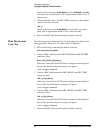
Verifying the Multiple Channel Controller
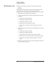
Counter Pulse Delay
Test
The following test determines if the on-board counter is operating correctly.
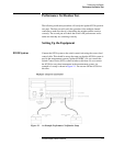
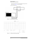
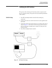
1. Connect BNC cables between the SRC1 TRIG, RCVR READY
connectors and the oscilloscope as shown in Figure 2-3 on page 2-10.
2. On the oscilloscope press:
[RECALL] [1]
[TRIG] {Source 2} {Adjust: 1.5v} { }
(+ Edge}
[TIMEBASE] {1 us/Div} {Delay: 4 us} {Ref: Centr}
[SAVE] [2]
3. Press the following on the multiple channel controller:
[Clear Instr] [Select Instr] {85330A} {RESET} [More] {TEST} {COUNTER}
4. Press the following on the multiple channel controller:
[4] [Return]
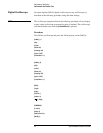
5. The negative edge of the displayed pulse should be 4 ±1 microseconds.
To use the scope measurement feature, press:
[∆t ∆v] {∆t Marker: ON}.
Rotate the front panel knob until the vertical marker line intersects the
negative edge of the pulse. Note that the Start Marker reading will be the
pulse delay. See Figure 2-4 on page 2-10 for more information.
6. On the oscilloscope press:
[TIME BASE] {1 us/Div} {Delay: 1000 us} [CLEAR DISPLAY]
7. Press the following on the multiple channel controller:
[1] [0] [0] [0] [Return]
8. The negative edge of the displayed pulse should be 1,000 ±
1 microseconds.
To use the scope measurement feature, press:
[∆t ∆v] {∆t Marker: ON}.
Rotate the front panel knob until the vertical marker line intersects the
negative edge of the pulse. Note that the Start Marker reading will be the
pulse delay. See Figure 2-4 for more information.
9. On the oscilloscope press:
[TIME BASE] {2 us/Div} {Delay: 15 ms} [CLEAR DISPLAY]
10. Press the following on the multiple channel controller:
[1] [5] [0] [0] [0] [Return]
11. The negative edge of the displayed pulse should be 15 ± 0.001
milliseconds.
To use the scope measurement feature, press:
[∆t ∆v] {∆t Marker: ON}.
Rotate the front panel knob until the vertical marker line intersects the