


85330A Multiple Channel Controller 4-5
General Information
Preparing the 85330A to Control the System
PIN switch modules
The switches are broadband, high-isolation switches. Each switch is
supplied with a switch control unit. Specifications and performance
characteristics are provided in the Agilent 85331A and Agilent 85332A PIN
Switch User’s Manual.
The Downloadable
Driver
The multiple channel controller cannot perform tasks until programming
instructions are supplied. These instructions specify:
• How to interact with the control boards installed in its rear panel slots.
• The softkey menu interface and the functions performed by each
softkey.
• The GPIB programming commands that setup and control the multiple
channel controller.
This driver is supplied by Agilent and is loaded into the multiple channel
controller at the factory. If you must ever re-load the driver, refer to the
instructions provided in Chapter 5, “Manual Operation.”
System Interface A system interface board (85330-60002) is installed in the back of the
multiple channel controller. This board contains the TTL trigger and ready
lines that interface to the receiver, switch control units, and (if using Fast
Source Control) the RF and LO sources.
Required Equipment The following equipment is required in addition to the 85330A:
• The cables that connect the 85330A, switch control units and switch
modules.
• One or more 85331A or 85332A PIN switch. The switches include their
associated switch control unit.
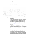
Cables 85383A Local Control Cable
Provides the connection between the multiple channel controller and each
SCU. Cable length is determined at the time of order by selecting the
appropriate length option.
• Option 002: 2 meters
• Option 005: 5 meters
• Option 010: 10 meters
• Option 020: 20 meters
• Option 030: 30 meters
• Option 040: 40 meters
• Option 050: 50 meters