


6-2 85330A Multiple Channel Controller
Programming
Definition of Terms
NOTE Please review the following terms before reading information in this chapter.
SCU address
At the factory, each Switch Control Unit is assigned an address called an
SCU address. When commands are sent out port 1 or port 2, they only affect
SCUs with the specified SCU address. SCU addresses are set using DIP
switches inside the SCU, and can be set to 0, 1, 2, or 3. In a standard system,
the factory default setting is 0. For custom-designed systems, refer to the
documentation that came with that system for SCU address numbers.
Daisy-chained SCUs may use the same SCU address.
Channel
Each switch module has either two or four possible switch positions, or
channels. If you purchased a switching system designed by Agilent, you also
have received a manual that applies specifically to that switch tree. That
document shows the channel numbers for each switch. If you have
purchased a “standard” system, then channels 1 through 4 are the factory
default channel numbers. (Channels 3 and 4 only apply to four-throw
switches.)
NOTE Ports 1 and 2 are addressed independently. Because of this, there are no
addressing conflicts when using two SCUs—even if they use the same SCU
address and channel numbers.
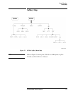
Switch address
This is the complete software address for a specific switch. It is simply a
concatenation of the SCU address (0, 1, 2, or 3) with the channel number
(usually 1, 2, 3, or 4, but possibly a number up to 64 in custom systems).
Examples:
@103 = SCU address 1 and channel 3 selected.
@2 = SCU address is 0 (and need not be specified), and channel 2 is
selected.
@232 = SCU address is 2 and channel 32 is selected (custom systems only).
The port number (1 or 2) is specified separately, as is explained later in this
chapter.