


85330A Multiple Channel Controller 6-5
Programming
Single Source Multiple-Frequency Configuration
Single Source Multiple-Frequency Configuration
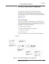
Description In single-source (8511A/B based) systems, the Fast Source Control mode is
not available. The RF source is controlled by the 8530A (Analyzer
Language mode). The proper setup is shown in Figure 1-2 on page 1-4.
The Fast Data Acquisition modes of the 8530A cannot be used with this type
of measurement. Instead, the multiple parameter display of the 8530A is
used to measure each switch input.
Refer to the programming “Example 2” on page 6-25.
NOTE When using the multiple parameter display feature, the minimum switch
settling time (RUNT:SWIT:DEL) is 50
µs. Using shorter settling times in
multiple parameter display mode can cause measurement problems
To Use this
Configuration
Here is an overview of how measurements are made in this configuration.
Remember, GPIB commands must be immediately followed by a semicolon
when entered into an actual program. For example
NUMEB1;.
8530A settings
• Select multiple parameter display mode on the 8530A. The number of
parameters selected should equal the number of test signals you are
measuring. For example, assume you have a two-throw receive switch
connected to two test signals. In this case, program the 8530A for two
parameter display GPIB command
TWOP. This is the equivalent of
pressing
[DISPLAY] {DISPLAY MODE} {TWO PARAMETER}.
• Set each parameter to measure the same input ratio. For example, set
them all to measure b1/a1. The numerator and the denominator are
defined below:
❍ The numerator is the input port (of the frequency downconverter)
that is connected to the common port of the receive switch. Set this
using the GPIB
NUMEB1, NUMEB2, NUMEA1, or NUMEA2 command. This is
equivalent to pressing PARAMETER
{MENU} {REDEFINE PARAMETERS}
{NUMERATOR},
then {NUMERATOR: b1}, {NUMERATOR: b2}, {NUMERATOR: a1}, or
{NUMERATOR: a2}.
❍ The denominator is the input port that is connected to the reference
signal. Use the
DENOA1, DENOA2, or DENOB1 command. This is
equivalent to pressing PARAMETER
{MENU} {REDEFINE PARAMETERS}
{DENOMINATOR}
, then {DENOM.: a1}, {DENOM.: a2}, or {DENOM.: b1}.