


2-6 Chapter2
Quick Start: Learning How to Make Measurements
Learning to Make Transmission Measurements
Learning to Make Transmission Measurements
This example procedure shows you how to measure the transmission response of a
10.24 GHz bandpass filter. The measurement parameters listed are unique to this
particular test device.
For further measurement examples, refer to the “Making Measurements” chapter in the
User's Guide.
Step 1. Choose the measurement parameters with your test device
connected
1. Press the key to return the analyzer to a known state.
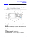
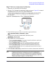
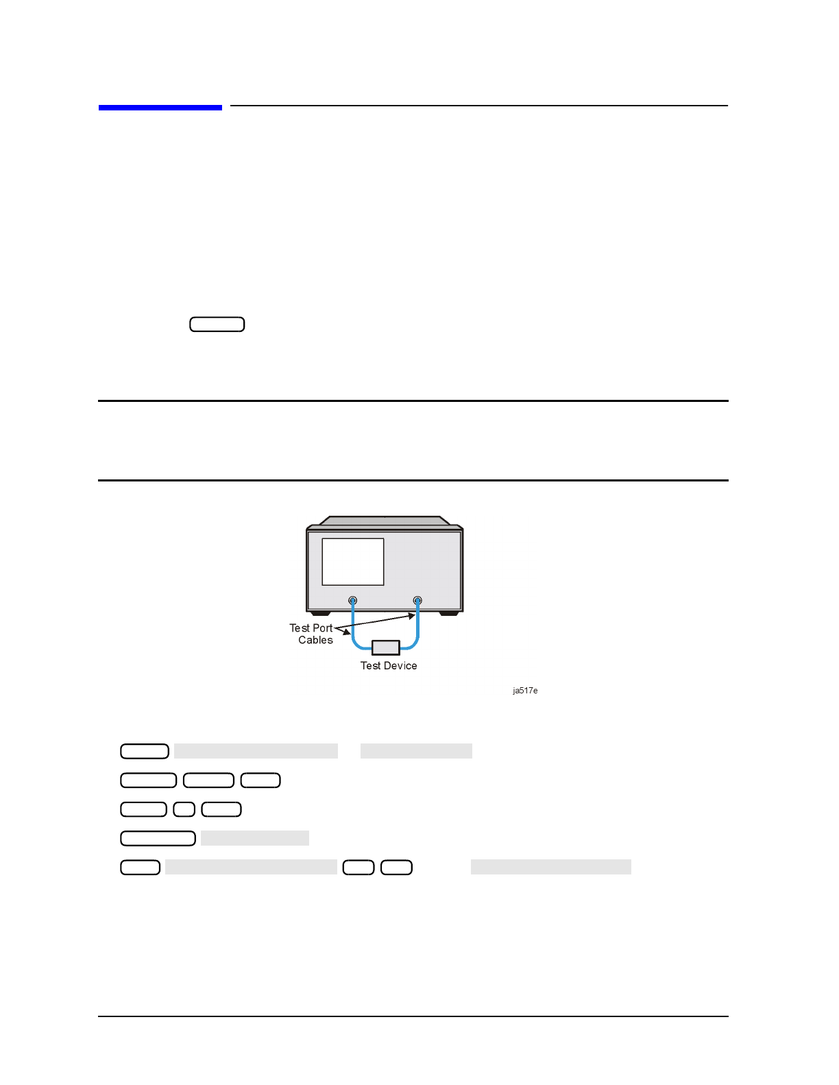
2. Connect your test device to the analyzer as shown in Figure 2-2. Use adapters where
appropriate.
CAUTION Damage may result to the device under test if it is sensitive to the analyzer's
default output power level. To avoid damaging a sensitive DUT, be sure to set
the analyzer's output power to an appropriate level before connecting the
DUT to the analyzer.
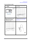
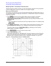
Figure 2-2 Device Connections for a Transmission Measurement
3. Choose the following measurement settings:
or
. Toggle until ON is
displayed.
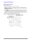
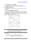
4. Look at the device response to determine if these are the parameters that you want for
your device measurement. For example, if the trace is noisy you may want to increase
the test port output power (which increases the analyzer input power), reduce the IF
bandwidth, or add averaging. Or, to better see an area of interest, you may want to
change the test frequencies.
Preset
Meas
Trans: FWD S21 (B/R)
TRANSMISSN
Center 10.24 G/n
Span 5 G/n
Scale Ref
AUTO SCALE
Avg
AVERAGING FACTOR
32 x1
AVERAGING on OFF